The basic relationship during resonance
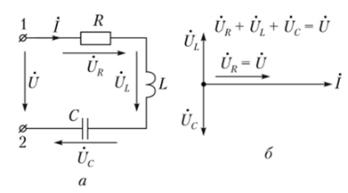
In the figure, a is a symbolic value model that includes series connected resistors, inductors, and capacitors. For the sake of certainty, let us assume that the complex number shown in the figure is a complex number of significant values.
This type of chain is widely used in engineering practice, but it is considered separately.

Series resonant circuit:
A symbolic model of a chain; Vector diagram during b-resonance
Due to the series connection of components in a given circuit, only series resonance can be observed. The complex input resistance of the circuit relative to terminals "1" and "2" is equal to

The resonance condition is the equal BX of the imaginary part of zero Z, that is

Therefore, during resonance, the reactance of inductance and capacitance are equal. Under the given parameters L and C, resonance occurs at frequency

The symbol 0 for the resonant frequency ω used here will be used in the following text.
The state of the chain is determined by an equation based on the second Kirchhoff's law:

At the resonant frequency, due to the equal reactance of inductance and capacitance, the voltage across the reactive element adds up to zero:

Therefore, the input voltage is equal to the voltage across the resistor. This situation is shown in the vector diagram.
The current in the circuit during resonance is represented by I0:

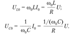
So the effective values of the voltages on the reactive elements L and C are the same when resonating U l0 and U co, and considering the relationship, they are equal to

According to the equation, if the resistance of the inductance and capacitance during resonance is greater than the resistance R, the voltage on the reactive element will exceed the input voltage.
For low loss (R small) circuits, the U L and U c values during resonance may exceed the input voltage by many times. In theory, the resonant current I0 and the voltage across the reactive element reach infinity.


