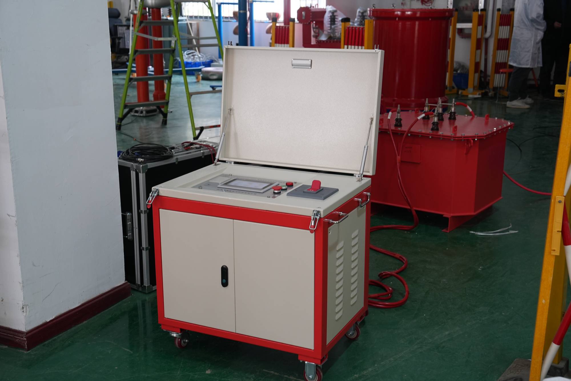
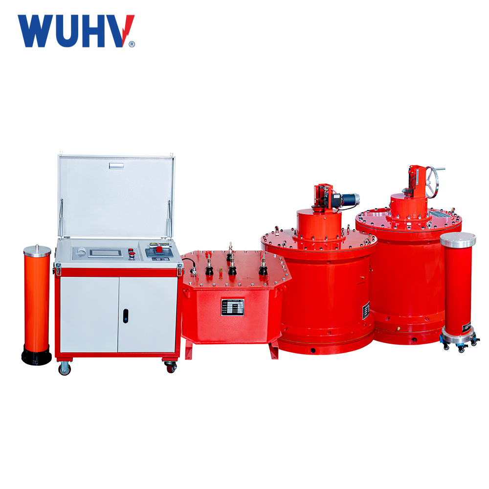
Capacitor inductor series resonant circuit? Wuhan UHV specializes in producing series resonant devices, with a wide range of product selection and professional electrical testing. When looking for series resonant devices, choose Wuhan UHV.
There are many components composed of inductors and capacitors in the power system, such as equivalent inductance of power transformers, mutual inductors, reactors, generators, etc; Series and parallel capacitor banks for compensation, ground and phase to phase capacitance of line conductors, and equivalent capacitance of various high-voltage equipment. The combination between them can form a series of oscillation circuits with different self oscillation frequencies, and under certain conditions, can form a long-lasting ferromagnetic resonance overvoltage.
In a series circuit composed of inductors and capacitors, when the capacitive reactance XC is equal to the inductive reactance XL, i.e. XC=XL, the phase of the voltage U and current I in the circuit are the same, and the circuit exhibits pure resistive behavior. This phenomenon is called series resonance. When a series resonance occurs in the circuit, the ideal impedance value at both ends of the circuit is Z=XC-XL=0, the total impedance in the circuit is minimized, and the current will reach its maximum value.
On the contrary, in a parallel circuit composed of inductors and capacitors, when the circuit undergoes series resonance, the ideal impedance value at both ends of the circuit is Z=∞, and the total impedance at both ends of the circuit is the highest. Therefore, the voltage at both ends of the circuit will reach its maximum value. This circuit has neither inductors and capacitors in series nor in parallel. It seems to be a thyristor voltage regulating circuit. The main function of inductance here is to suppress high-frequency interference currents (the property of inductance is that the higher the frequency, the greater the reactance). The capacitor on top plays a filtering role, smoothing the triggering voltage for the thyristor trigger diode anode and eliminating high-frequency interference (while also being a part of obtaining the triggering voltage); The capacitor below is a bypass capacitor, mainly added for the normal start-up of the circuit.
When parallel resonance occurs, the voltage on the inductor and capacitor is equal to the power supply voltage, and the resonance current is many times higher than the total current. During series resonance, the voltage on the inductor or capacitor is many times higher than the power supply voltage. Some series resonant circuits may look like parallel resonance, but in fact they are series resonant circuits. The key to determining whether it is a series or parallel resonance is to see which two ends the power or signal source is sent to. For example, in the intermediate frequency amplifier circuit of radios and televisions, in the primary stage of the intermediate frequency transformer, the signal is applied to both ends of the LC parallel circuit, resulting in parallel resonance. On the secondary coil of the same transformer, a capacitor is often connected in parallel, which may appear to be parallel resonance, but in fact it is series resonance because the signal is induced from the secondary coil and is connected in series with the signal in the LC circuit, rather than being added to both ends of the LC parallel circuit.
The resonance phenomenon is a specific working state of a sinusoidal steady-state circuit. Usually, resonant circuits are composed of capacitors, inductors, and resistors, and can be divided into series resonant circuits, parallel resonant circuits, and coupled resonant circuits. But this article mainly focuses on the study of series resonance. Due to the good selectivity of resonant circuits, the phenomenon of inductance voltage or capacitance voltage being greater than the excitation voltage during series resonance has been effectively applied in the field of wireless communication technology. When tuned at a certain frequency or frequency band, the signal within that frequency or frequency band can be particularly enhanced, while filtering out signals in other frequencies or frequency bands. This performance is called the selectivity of resonant circuits.
When a series resonance occurs in a circuit, the voltage on the capacitor and the voltage on the inductor are equal in magnitude and opposite in direction. All power supply voltages (or signal source voltages) are equivalent to being added to the equivalent series resistance of the circuit. The smaller the equivalent resistance, the greater the total current in the circuit. The impedance of the capacitor and inductor remains constant, and the voltage on them is equal to the reactance X current. So, the voltage on inductors and capacitors can be very high, up to hundreds or even thousands of times the power supply voltage. This multiple is called the quality factor of the resonant circuit. It directly represents the quality of the resonant circuit. The higher the quality factor, the smaller the loss of the resonant circuit.
The quality factor in resonant circuits can generally reach around 100. It can be seen that the voltage on the inductor and capacitor is many times higher than the power supply voltage, so series resonance is also called voltage resonance. The smaller the resistance of the coil, the less energy the circuit consumes, indicating good circuit quality and high quality factor; If the inductance L of the coil is larger, the more energy is stored, and when the loss is constant, it also indicates that the circuit quality is good and the quality factor is high. So in electronic technology, due to weak external signals, series resonance is often used to obtain a voltage that is the same frequency as the signal voltage but many times larger.


