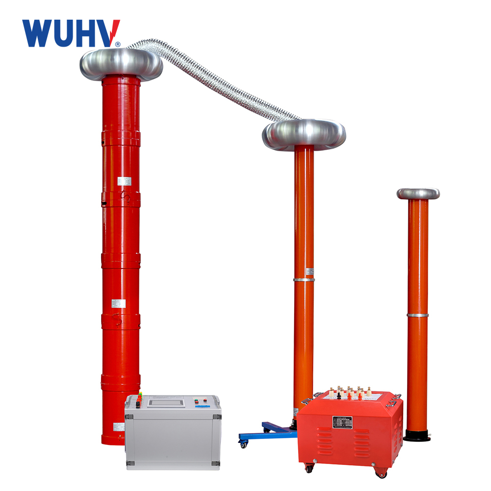
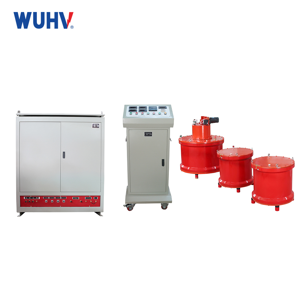
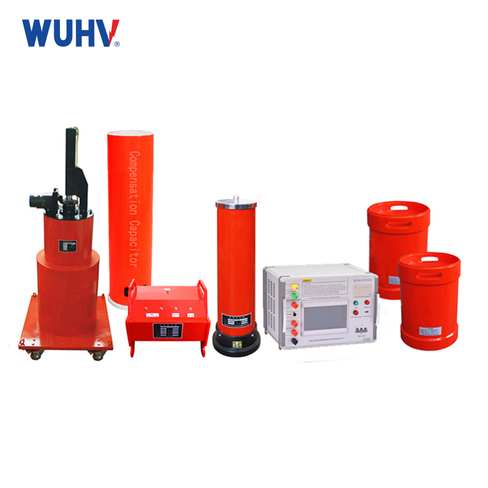
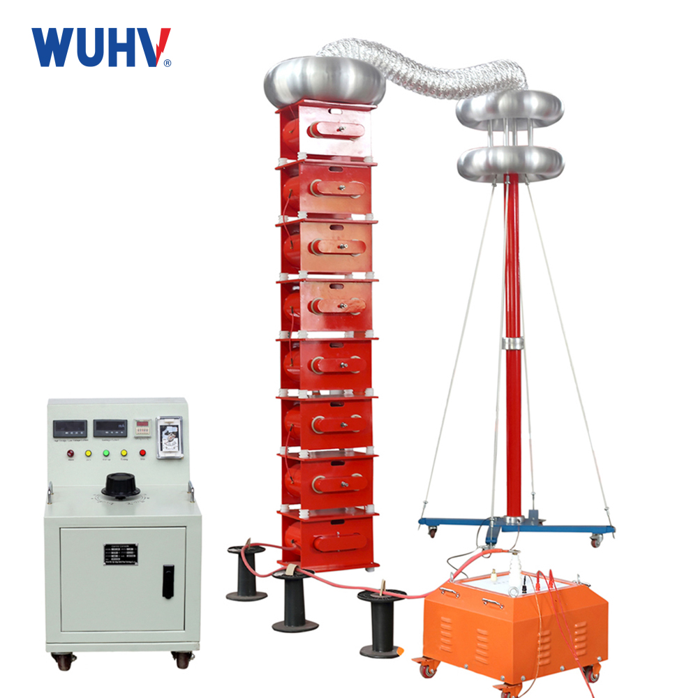
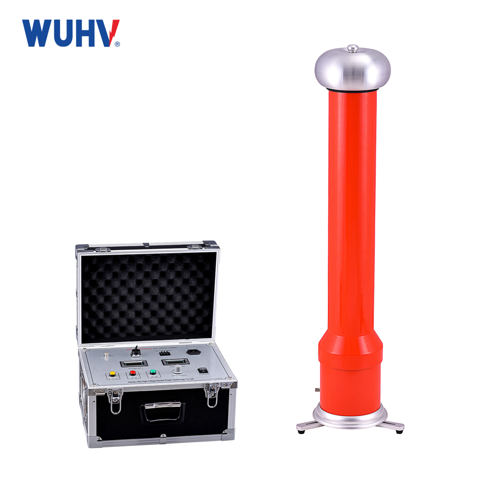
The series resonanceunder UHV power can help many power workers conduct various power tests more conveniently.
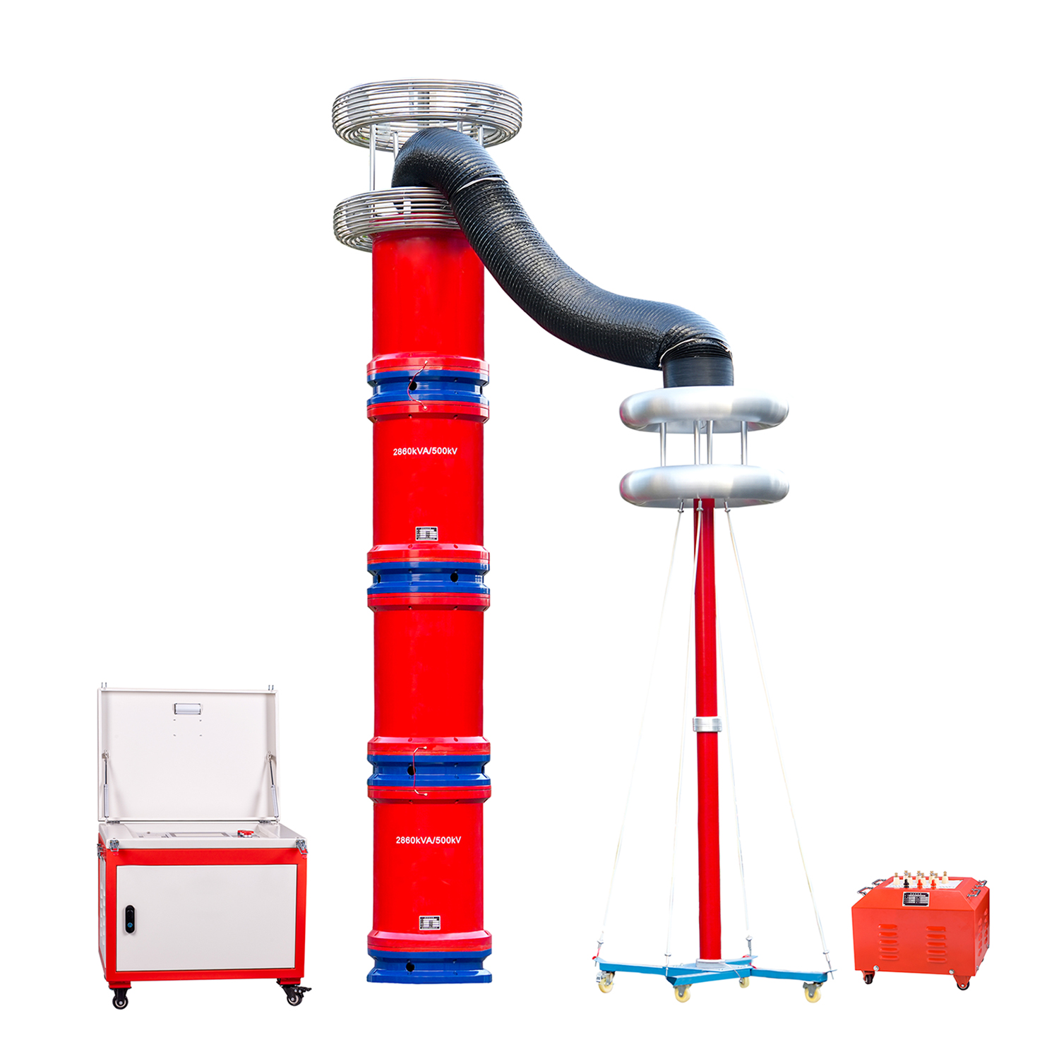
When a series circuit resonates in practical applications, it is necessary to consider both the selectivity of the circuit and the ability of the circuit to allow signals to pass through within a certain range. So what exactly is a series resonant circuit? What are the characteristics of a series resonant circuit? Below is an analysis for everyone.
1. Series resonant circuit
In an AC circuit with resistor R, inductor L, and capacitor C components, the voltage at both ends of the circuit is generally different in phase from the current in it. If the parameters or power frequency of circuit components (L or C) are adjusted, they can be made to have the same phase, and the entire circuit appears purely resistive. When a circuit reaches this state, it is called resonance. In the resonant state, the total impedance of the circuit reaches or approximates its maximum value. There are two types of circuit connections: series resonance and parallel resonance. Science and applied technology should fully utilize the characteristics of resonance while also preventing the harm it may cause.
Characteristics of series resonance: The circuit is purely resistive, with the terminal voltage and total current in phase. At this time, the impedance is the smallest and the current is the largest. It may generate high voltages on the inductance and capacitance that are many times greater than the power supply voltage. Therefore, series resonance is also known as voltage resonance. In power engineering, due to the occurrence of overvoltage and high current caused by series resonance, which can damage electrical equipment, it is necessary to avoid series resonance.
2. Characteristics of series resonant circuit:
a. The circuit impedance Z is the smallest and pure resistance, and Z=R
b. The current I in the circuit reaches its maximum value and is the same as the power supply voltage. The current at which the circuit undergoes series resonance is called the resonance current, represented by Io. When the power supply voltage is constant, the occurrence of series resonance can be determined by whether the current of the RLC series circuit reaches its maximum value.
c. The voltage on L and C is equal in magnitude, opposite in direction, and cancels each other out
Therefore, series resonance, also known as voltage resonance, has an equivalent impedance of 0 at both ends of the inductor and capacitor during resonance, which is equivalent to a short circuit.
d. The voltage on the resistor is equal to the power supply voltage and reaches its maximum value.
e. Power
Active power: The power generated by the power source and the power consumed by the circuit resistance, with the maximum power.
Reactive power: During resonance, the circuit does not absorb reactive power from the outside. But there is a periodic exchange of magnetic field energy and electric field energy between the inductance and capacitance inside the circuit.
3. Advantages of series resonance test device:
1. High stability and reliability. The system adopts imported power components as the core of power conversion, with stable voltage and frequency output, reasonable electromagnetic compatibility design, and complete protection functions. After multiple high-voltage direct to ground short circuit tests, the system still remains intact, and at the same time, the system also has strong overload capacity
2. The automatic tuning function is powerful. When the system is automatically tuned, it automatically scans from 30Hz to 300Hz and displays the sweep curve, allowing users to intuitively see the tuning process of the system; After the frequency sweep is completed, the system performs a fine frequency sweep with a resolution of 0.01Hz within its ± 5Hz range based on the resonance frequency point preliminarily found by the sweep, and finally precisely locks the resonance frequency
3. Support multiple experimental modes. The system supports test modes such as "automatic tuning+manual voltage adjustment", "automatic tuning+automatic voltage adjustment", "manual tuning+manual voltage adjustment", etc. It is recommended to use the "automatic tuning+manual voltage adjustment" mode, which can quickly find the resonance point and control the test process through manual voltage adjustment, with higher safety.
4. The system has a user-friendly human-computer interaction interface. The experimental parameter settings, experimental control, and experimental results are displayed on the same screen, which is intuitive and clear, and has automatic timing and operation prompt functions. Full touch screen operation and display, with the function of saving and querying test data
Note: When resonance occurs in the RLC series circuit, the voltage across inductor L and capacitor C is Q times the applied power supply voltage. In general, series resonant circuits meet the condition of Q>1. In practical engineering, attention should be paid to avoiding damage to the circuit caused by high voltage due to series resonance.


