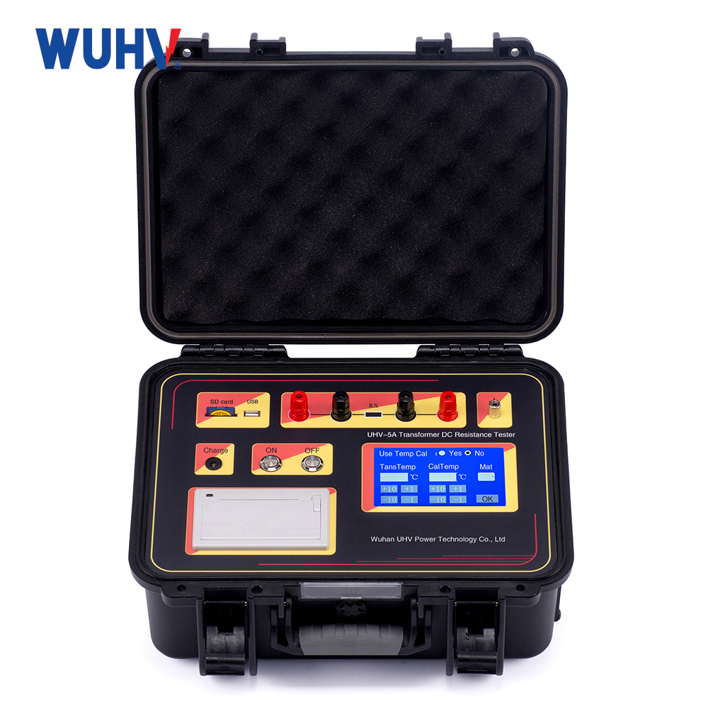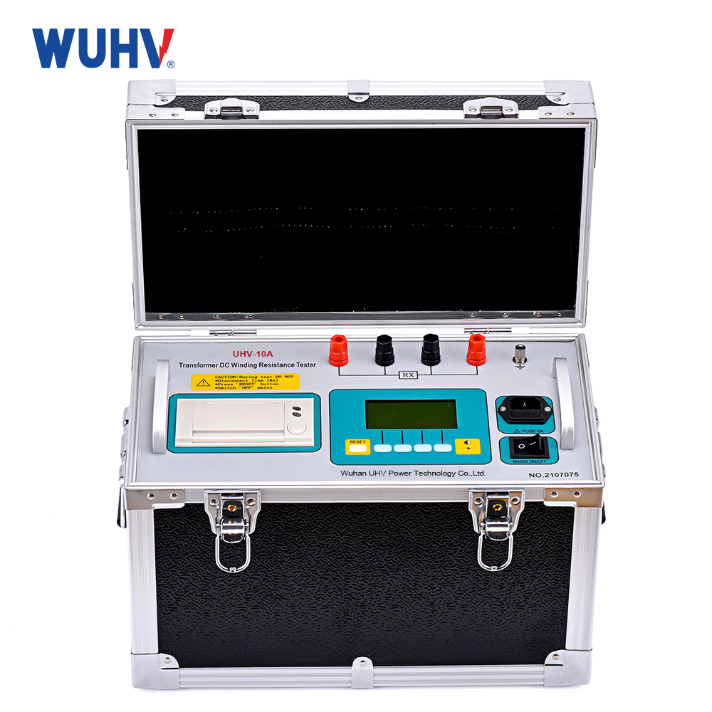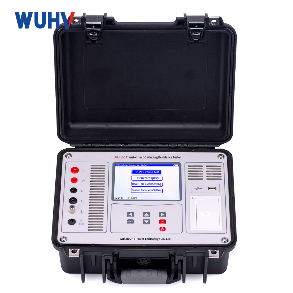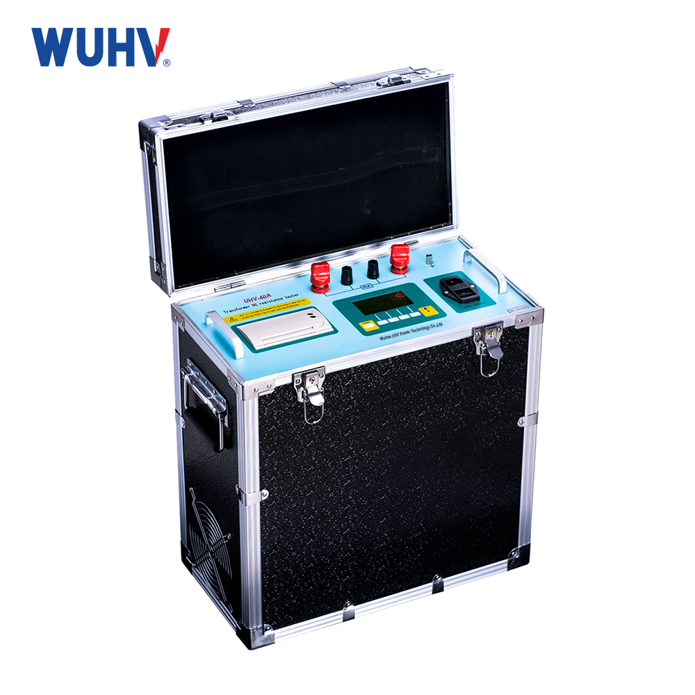
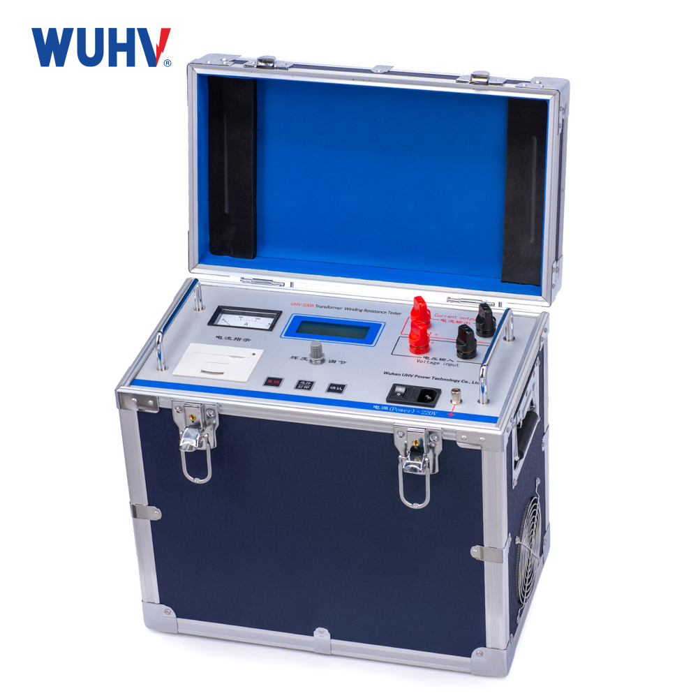
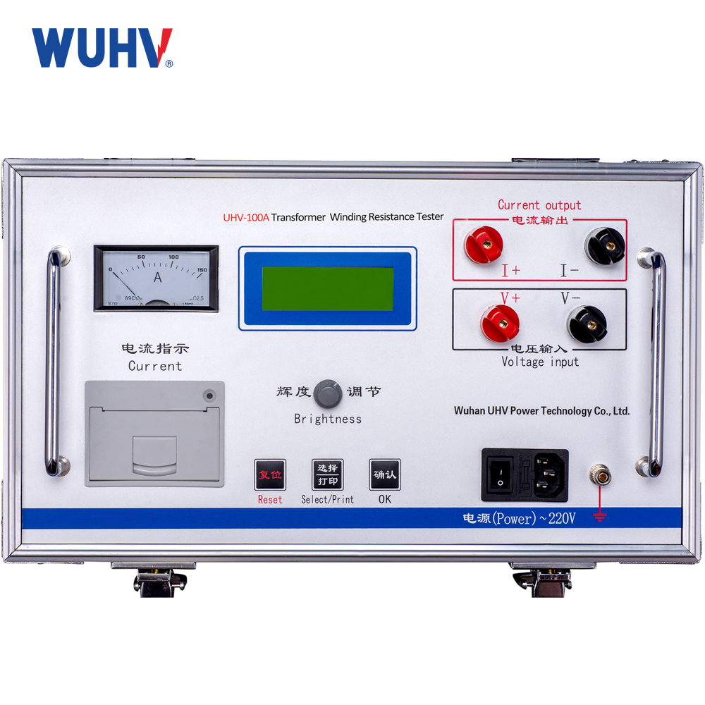


Product Introduction
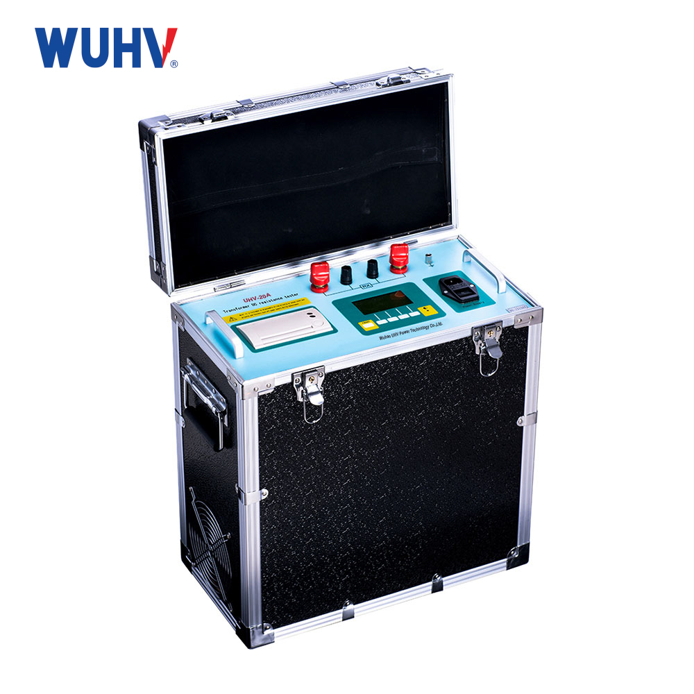
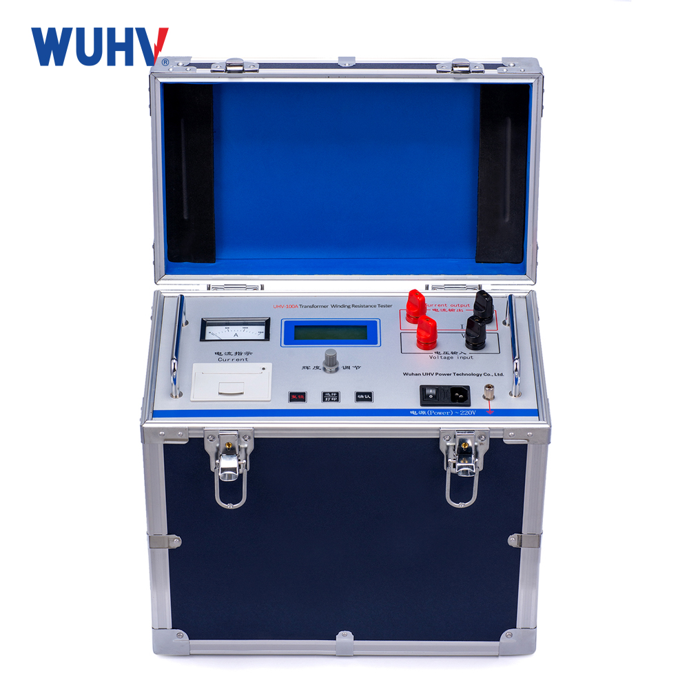
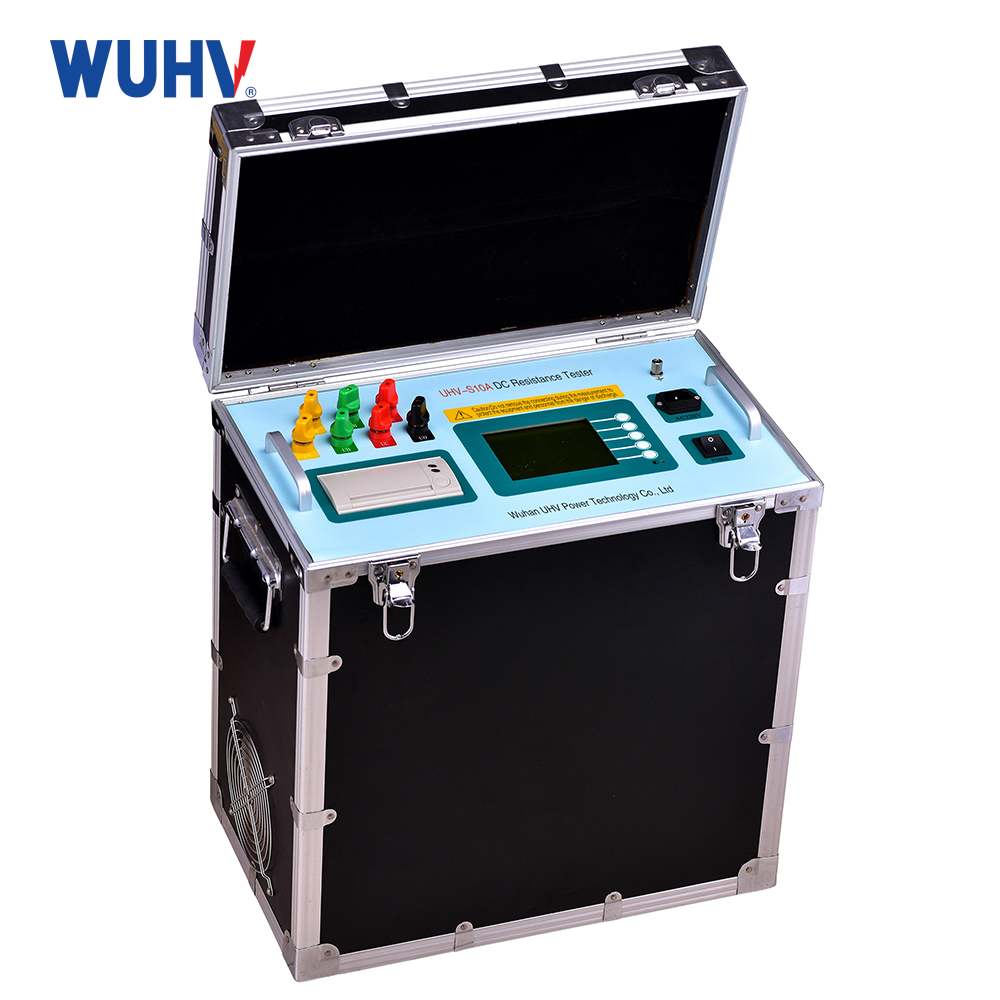
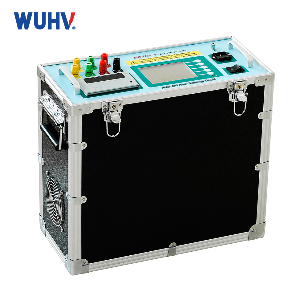
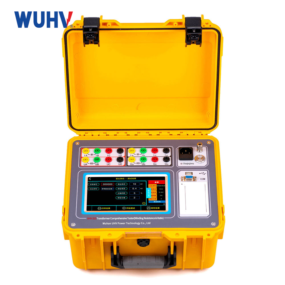
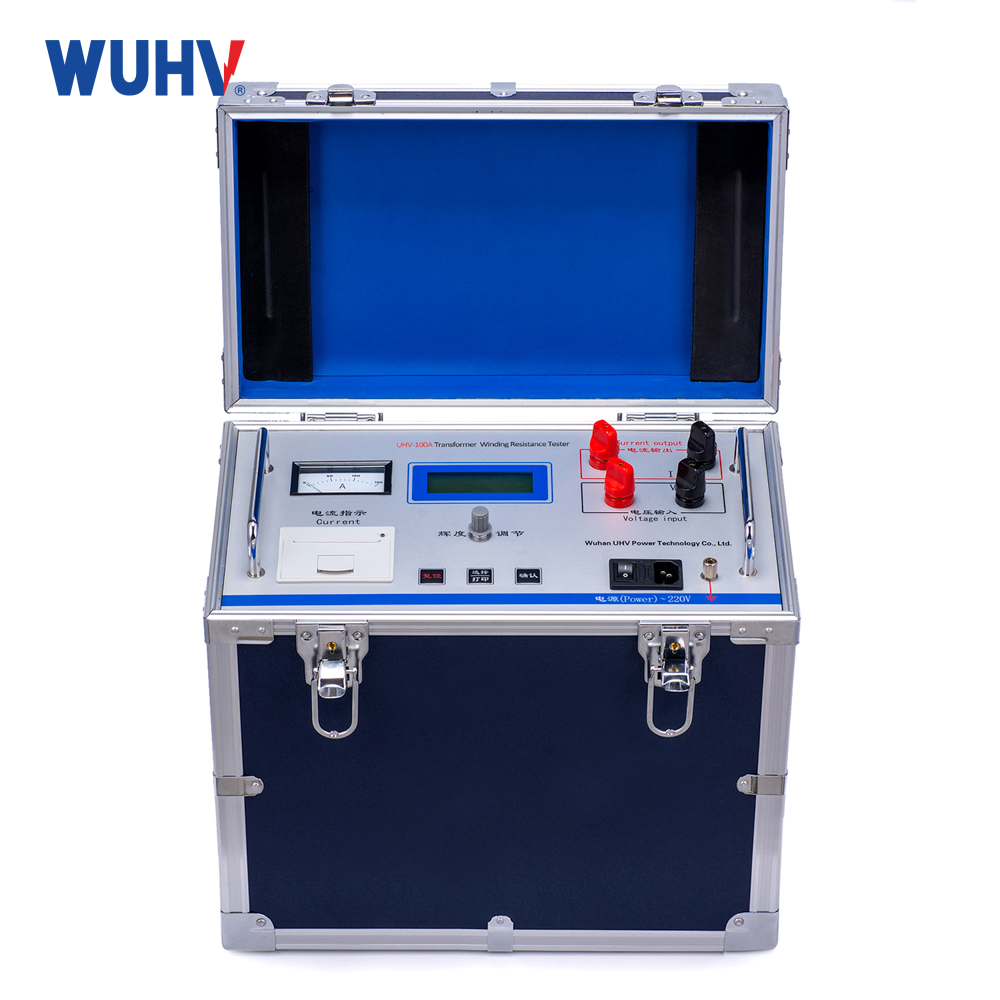
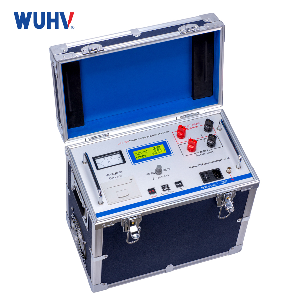
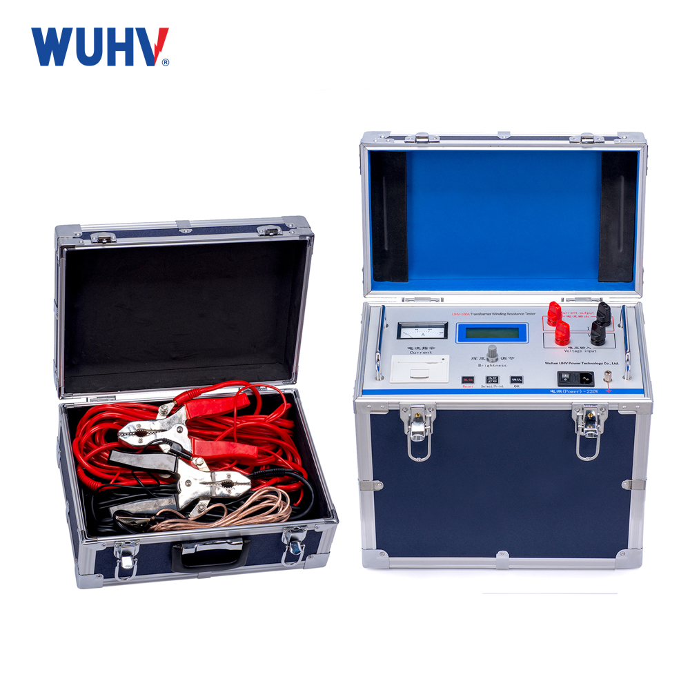
Transformer DC Resistance Tester is a necessary test project of transformer manufacturing for semi-finished products and finished products, including factory test, installation, overhaul, pick up switch, pick up test and preventive test of electric power department. You can check whether the welding of the group pick upquality and the turn-to-turn short-circuit of the winding of the group, check whether the pick up touch is good at various positions of the sub-pick up switch in voltage, and whether the actual position of the sub-pick up switch is consistent with the indicating position, so as to draw out whether the line is broken, and whether the multi-strand guide line and winding are broken, etc. In order to meet the needs of full transformer dc resistance fast measurement, our company develops a transformerDirect resistance test apparatus. Transformer DC Resistance Tester is adopts new power supply technology, featuring small volume, light weight, large current output, good repeatability, strong anti-interference ability and perfect protection function. The whole machine is controlled by high speed single chip microcomputer, with high degree of automation and automatic discharge and discharge alarm functions. Instrument test precision is high, operation is simple, and transformer direct resistance can be implemented with fast measurement.
Product functions
1. High-precision DC winding resistance measurement
The equipment outputs a stable DC current to the winding under test and employs the four-terminal (Kelvin) measurement technique to accurately measure winding resistance from micro-ohm to ohm levels.
Primarily used to detect:
Winding DC resistance values
Three-phase resistance balance
Conductor continuity
Connection and soldering quality
2. Multiple test current output levels
Depending on the transformer capacity, the equipment provides multiple output current options:
1 A,5 A,10 A,20 A,40 A,50 A,100A.
Higher output currents can shorten the magnetization time for large transformer windings, improving test efficiency.
3. Automatic current stabilization and fast testing
Designed for inductive loads, the tester automatically regulates the output current to quickly reach a stable state.
Its advantages include:
Shortened waiting time
Improved measurement repeatability
Reduced human judgment errors
Enhanced on-site testing efficiency
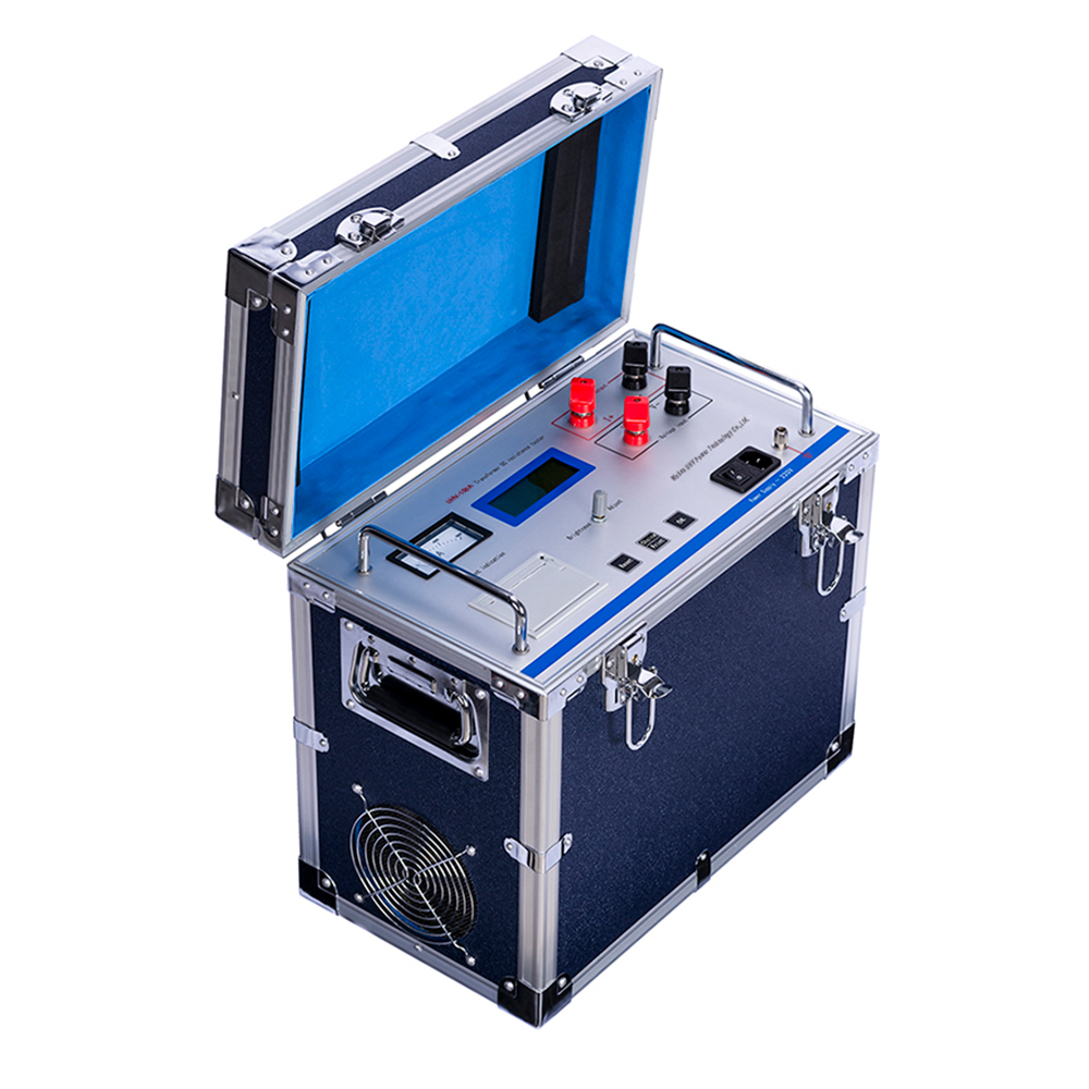 | 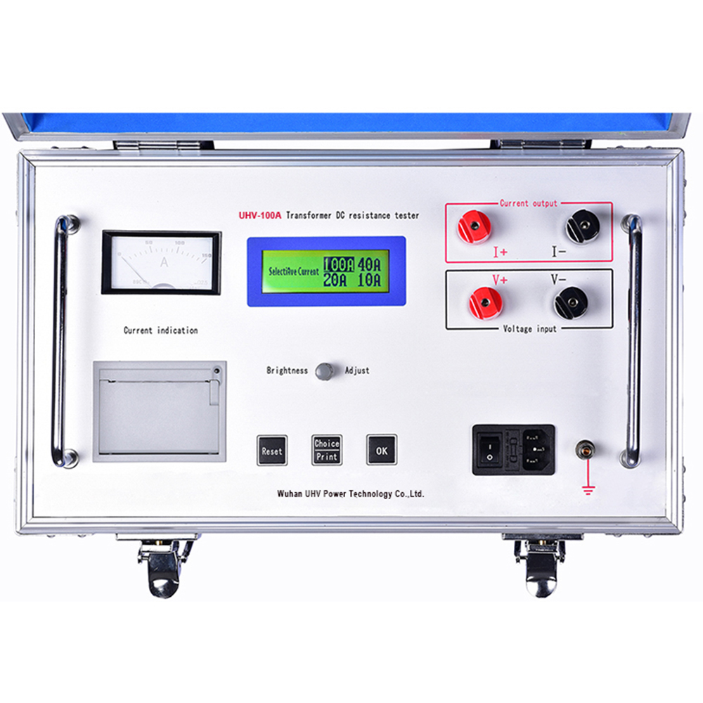 |
teknik parametreler
| Current range and range | 100A | 10μΩ~100mΩ |
| 40A | 50μΩ~500mΩ | |
| 20A | 100μΩ~1Ω | |
| 10 A | 500μΩ~2Ω | |
| 5A | 1mΩ~4Ω | |
| Kesinlik | ± (0.2%±2 words) | |
| Çözünürlük | 0,1 mΩ | |
| Ortam nemi | -10℃~40℃ | |
| Bağıl nem | ≤80%RH No condensation | |
| Çalışma güç kaynağı | AC220V±10% 50Hz | |
Product Characteristics
1、Whole machine is controlled by high-speed single-chip microcomputer, with high degree of automation and simple operation
2、Application of high frequency switch power supply technology, suitable for large and medium-sized transformerdc resistancemeasurement with large current output
3、Perfect protection function, can reliably protect the impact of counterpotential to instrument, and the performance is more reliable
4、with sound discharge alarm, clear discharge indication, reduce misoperation
5、With fast response time, the measurement state can be used to directly pick up switch with load points, and instrument can automatically refresh data
6、The vertical chassis structure is adopted to facilitate the use of scene
7、Intelligent power tube technology: instrument always works in the minimum power state, effectively reducing the heat inside instrument and saving energy. Work for hours without interruption
8、Dot matrix LCD, Chinese menu, printout
Application Scenarios
1. Factory testing and quality inspection of power transformers
After production is completed for distribution transformers, oil-immersed transformers, dry-type transformers, and large power transformers, DC resistance measurement is performed on high-voltage, low-voltage, and each tap winding to verify winding connection quality, soldering workmanship, and three-phase resistance consistency, ensuring products meet factory technical standards.
2. Substation equipment installation, commissioning, and acceptance
Before commissioning newly built or expanded substations, perform on-site winding DC resistance testing on transformers to check for winding damage, wiring abnormalities, or poor tap changer contact during transportation and installation, providing a reliable basis for safe equipment commissioning.
3. On-load tap-changer (OLTC) condition assessment
For maintenance and overhaul of on-load tap-changers in power transformers, measure winding resistance variations at different tap positions to evaluate switching mechanism and contact condition, promptly identifying potential faults such as increased contact resistance, contact wear, or unstable contact.
4. Power grid preventive testing and condition-based maintenance
During annual grid maintenance, preventive testing, and condition-based maintenance, perform periodic winding DC resistance testing on in-service transformers. By comparing with historical data, determine whether there are issues such as inter-turn short circuits, broken strands, loose connections, or aging in the windings, enabling equipment health condition assessment.
5. Maintenance testing of main and auxiliary transformers in power plants
Applicable for maintenance testing of main transformers, auxiliary transformers, and excitation transformers in thermal, hydro, nuclear, and new energy power plants. High-precision DC resistance measurement verifies winding and lead connection conditions, improving operational reliability of critical power equipment.
6. Maintenance of large electrical equipment in industrial enterprises
Widely used in steel, petrochemical, mining, cement, and rail transit industries for periodic testing of large power transformers, reactors, motor windings, and other equipment, helping maintenance personnel quickly locate winding defects and reducing the risk of unplanned outages.
7. Power equipment repair and major overhaul acceptance
After transformer factory repair, winding rewinding, lead replacement, or major overhaul completion, DC winding resistance testing verifies repair quality and confirms that winding parameters for each phase have returned to normal, providing technical basis for returning the equipment to service.
FAQs
Q: What is a transformer DC winding resistance tester? Why is it an important device in transformer testing?
A: A transformer DC winding resistance tester is a specialized testing device that calculates winding DC resistance by applying a stable DC current to the windings and measuring the voltage drop. It is primarily used to evaluate the electrical continuity of winding conductors, lead connections, and tap changers. It can help identify issues such as poor contact, broken conductor strands, soldering defects, and three-phase resistance imbalance. It is an important testing tool in transformer factory testing, acceptance inspection, and preventive maintenance.
Q:What types of equipment are suitable for use with the transformer DC winding resistance tester?
A: This equipment is not only suitable for oil-immersed transformers, dry-type transformers, auto-transformers, and distribution transformers, but is also widely used for reactors, generator stator windings, large motors, and other inductive power equipment. For any equipment that requires inspection of winding connection quality, conductor integrity, or tap changer condition, the DC winding resistance tester can be used for testing.
Q: Does temperature variation affect winding resistance test results?
A: Yes. The resistance of both copper and aluminum conductors changes with temperature, so data measured at different ambient temperatures cannot be directly compared. Typically, test results need to be converted to a unified reference temperature in accordance with international or industry standards, in order to facilitate historical trend analysis and condition assessment of the equipment.
Security measures
1. Before using this instrument, it is necessary to carefully read the instruction manual.
2. The user of the instrument should have general electrical knowledge.
3. Avoid using the instrument in places where it is exposed to rain, corrosive gases, excessive dust, high temperatures, direct sunlight, etc.
4. The instrument should avoid long-term bumps and severe vibrations.
5. Maintenance and debugging of instruments should be carried out by professionals.
6. After the test is completed, be sure to wait for the discharge alarm sound to stop before turning off the power and removing the test line.
7. When measuring an unloaded voltage regulating transformer, be sure to wait for the discharge indicator alarm sound to stop before switching gears.
8. During the testing process, it is prohibited to move the test clamp and power supply line.
Precautions
1. Before testing the no-load tap changer of the transformer, it must be reset. After the discharge is completed, the alarm sound should stop for more than 10 seconds before switching the tap changer.
2. Before disconnecting, be sure to wait for the discharge to end and the alarm sound to stop. It is best to wait for more than 10 seconds before disconnecting to ensure that the charge is completely released.
3. When selecting the current, refer to the range in the technical specifications column and do not use it beyond or below the range. When the current exceeds the preset value, the instrument remains in the "charging" state. When the range is insufficient, it displays' current too low '. When these two states occur, confirm the range and select the appropriate current for testing.
4. Pay attention to the range when using the magnetic assist method. Because two high-voltage coils are connected in parallel and one is connected in series, 1.5 times the resistance of the high-voltage coil is added to the entire testing circuit, and the range selection needs to be taken into account. If the output current cannot reach the set value or is unstable when using beyond the range.
5. When the short contacts of the three wires of the magnetic assist method are removed after discharge, there may be residual current, which may cause ignition and discharge during removal. This is a normal phenomenon.
6. When connecting the test clamp to the lead out terminal of the transformer winding, it is important to note that the lead out terminal is exposed to air for a long time, and the surface of the lead out terminal is covered with an oxide film, which may cause unstable or inaccurate measurement results. Therefore, when wiring, attention should be paid to cleaning the oxide film, or after connecting the test clamp to the lead out terminal, twist the test clamp vigorously a few times to cut through the oxide film to ensure a good connection.