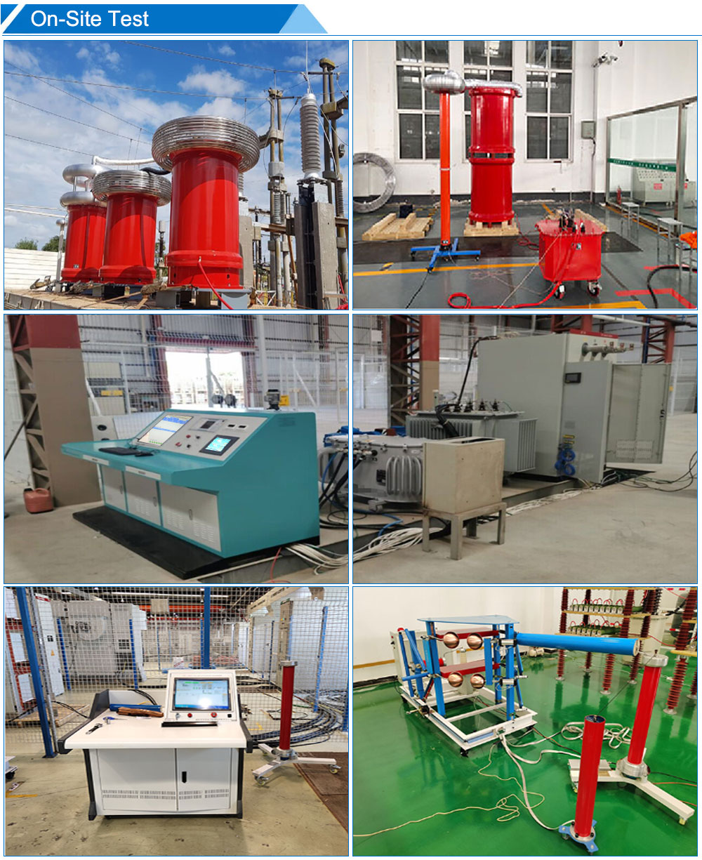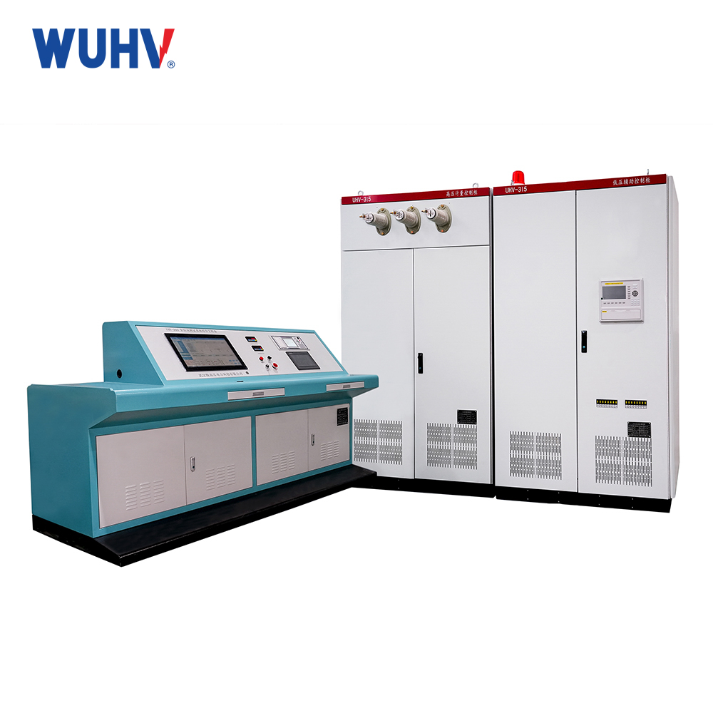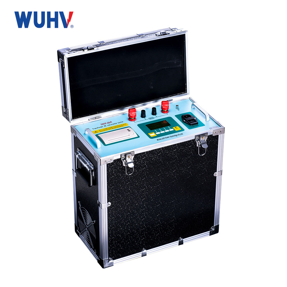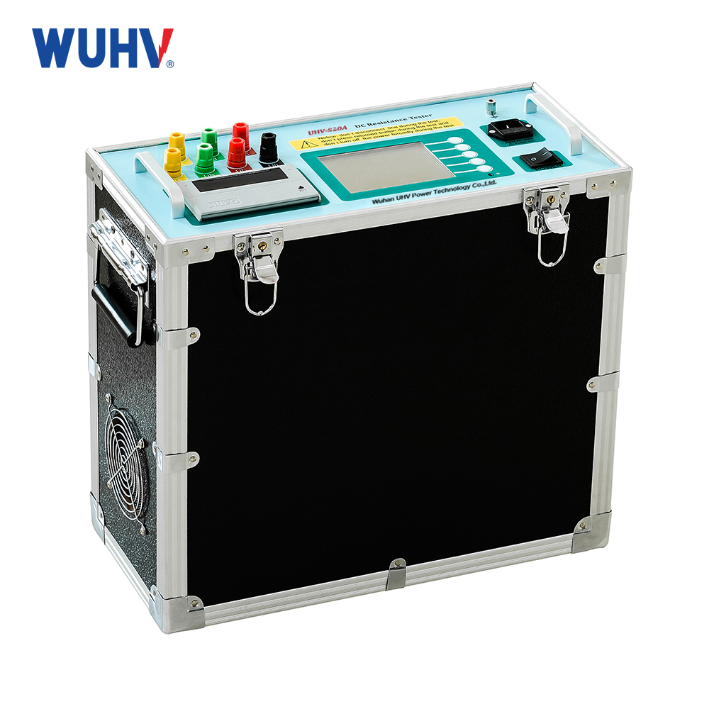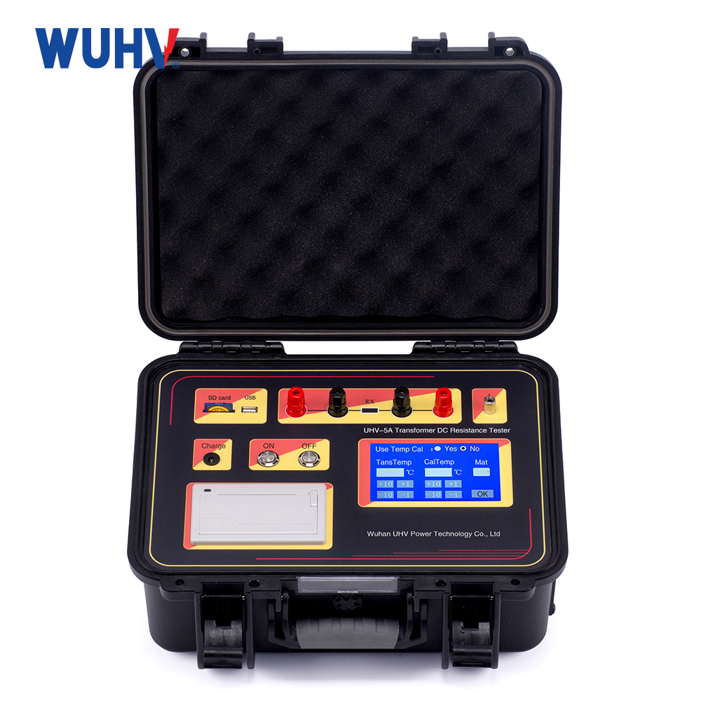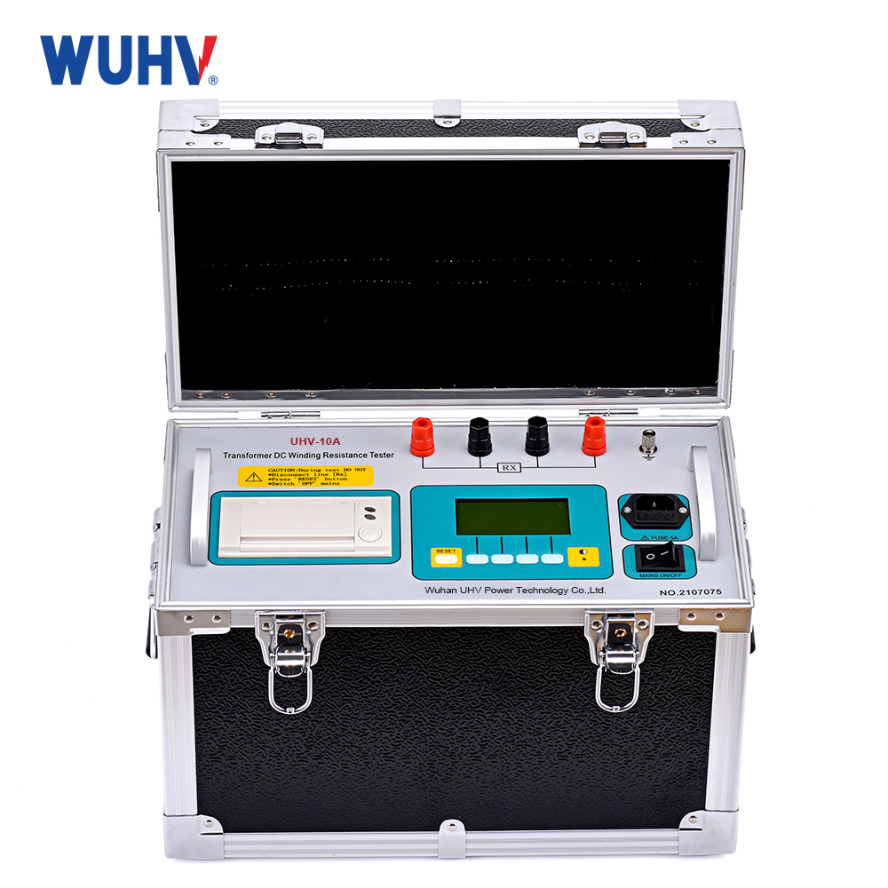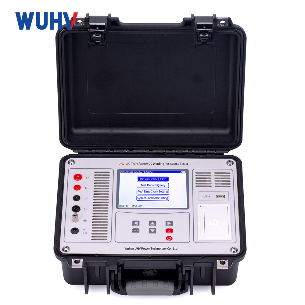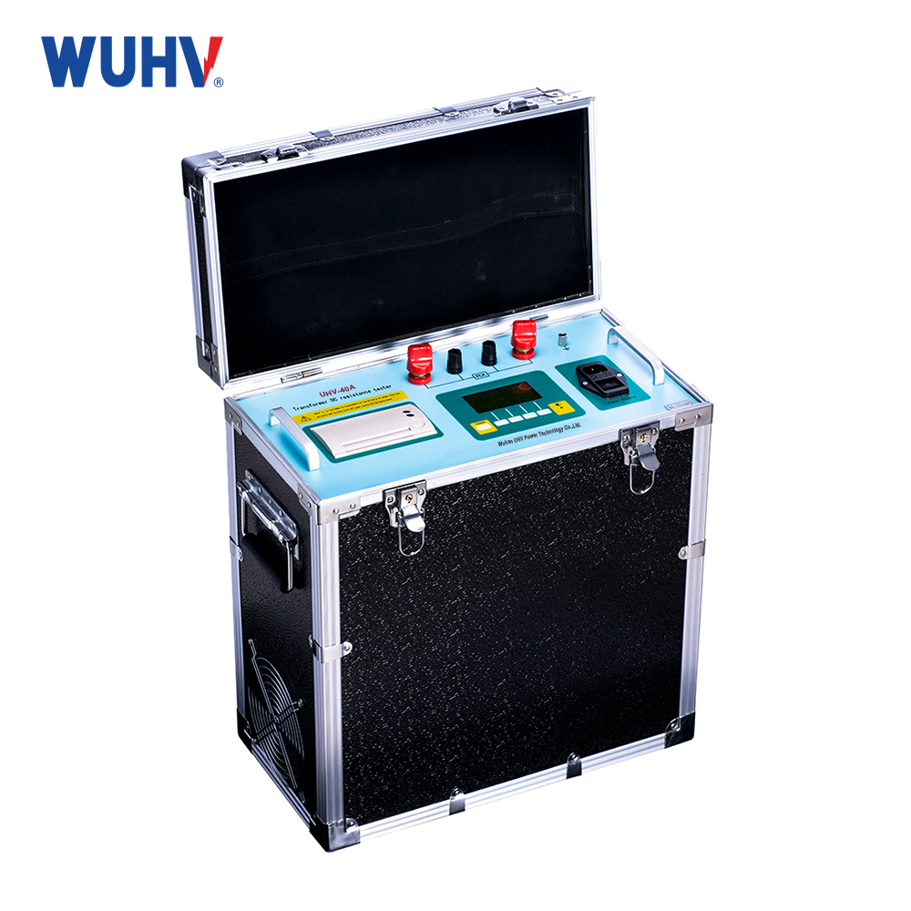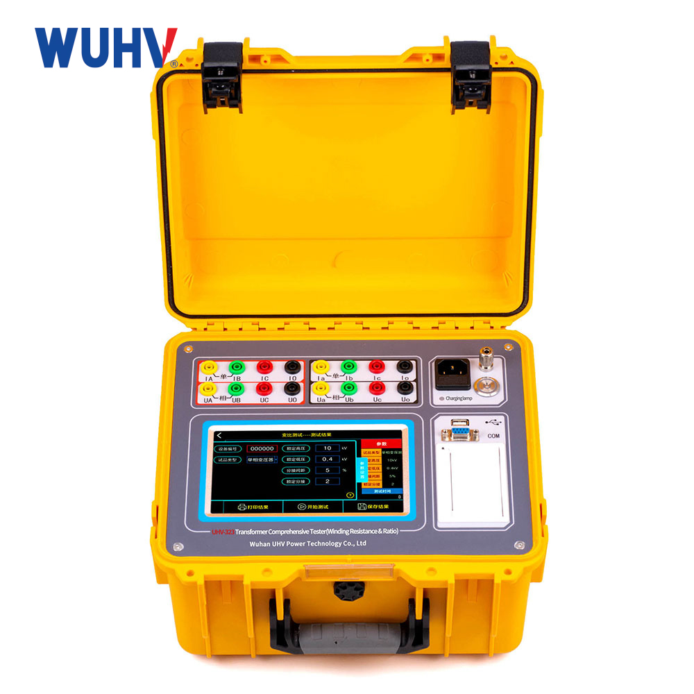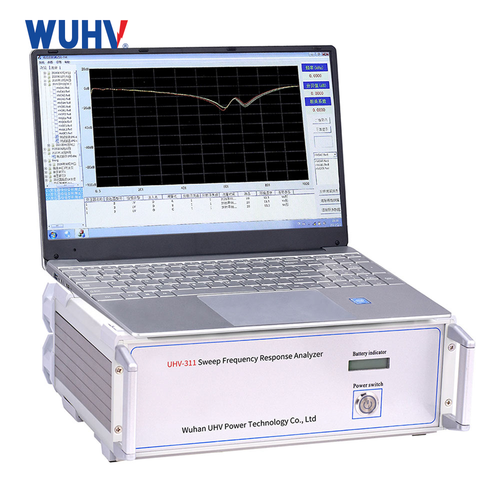
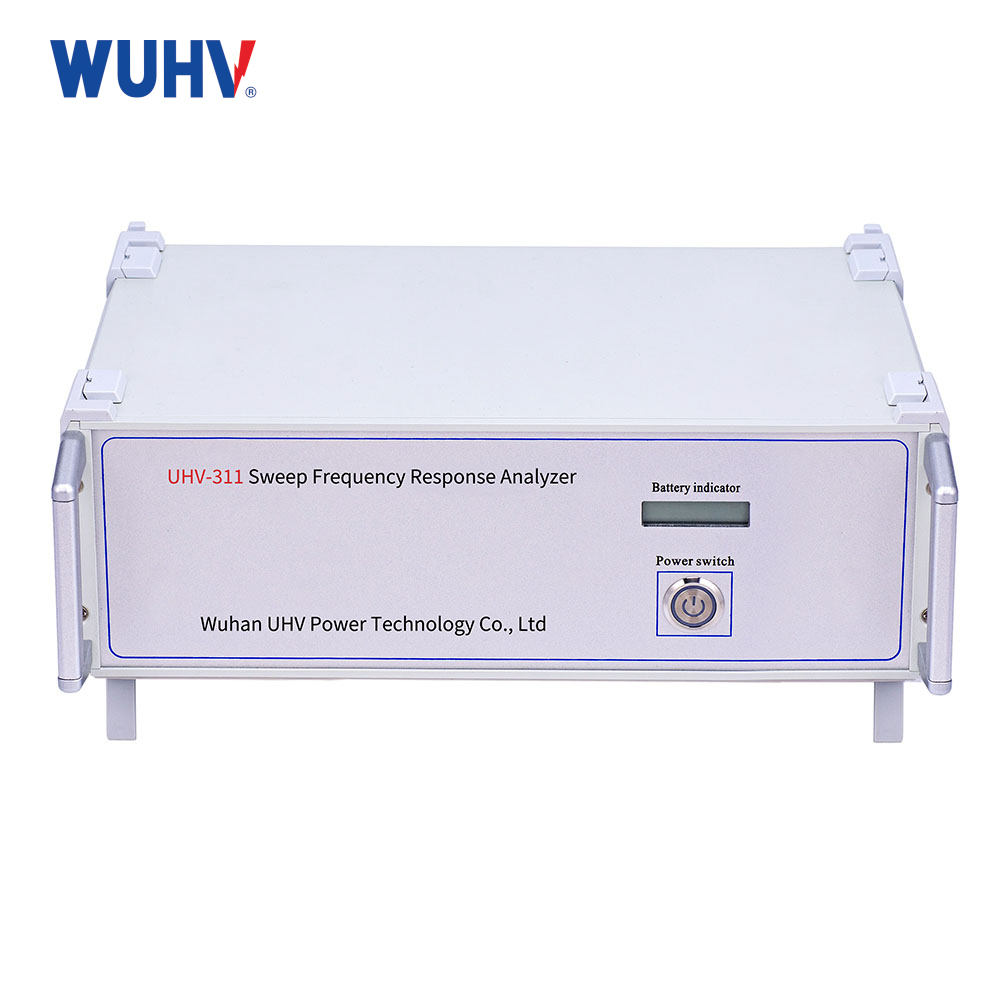
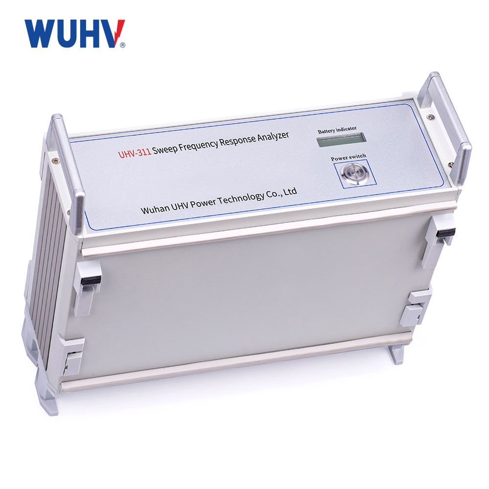
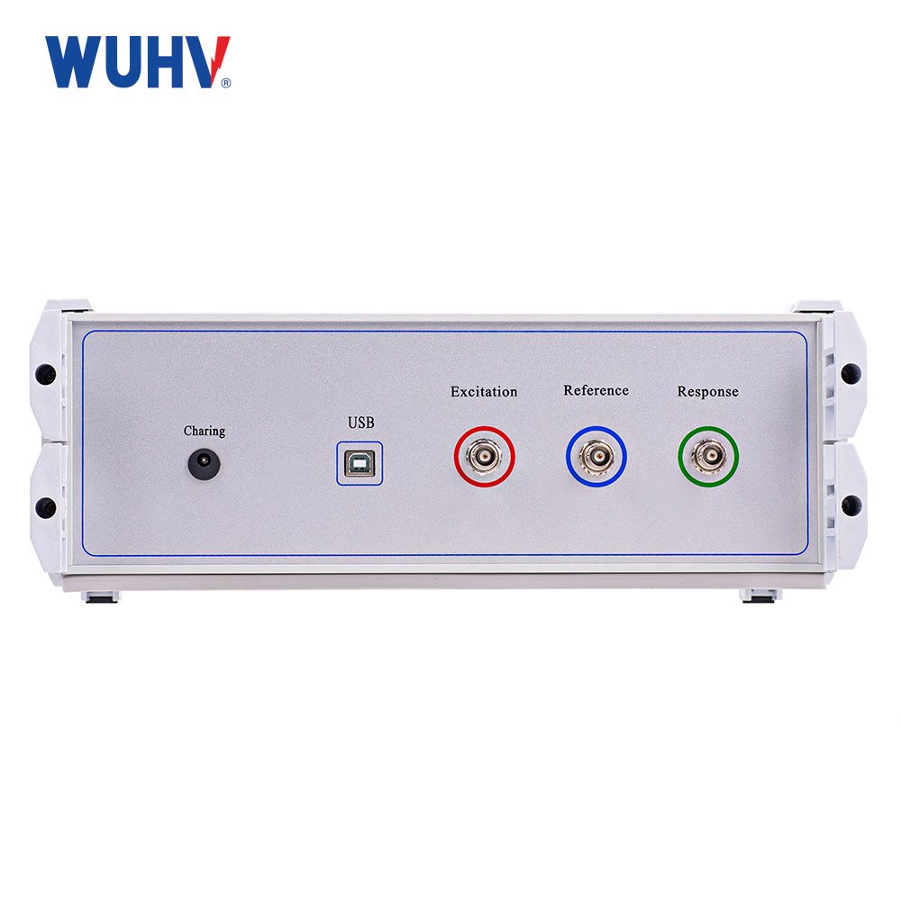
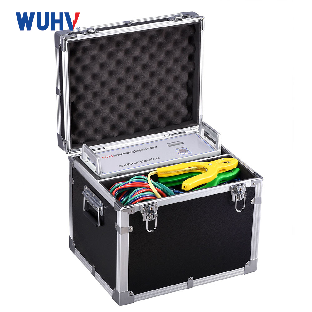


Product Introduction
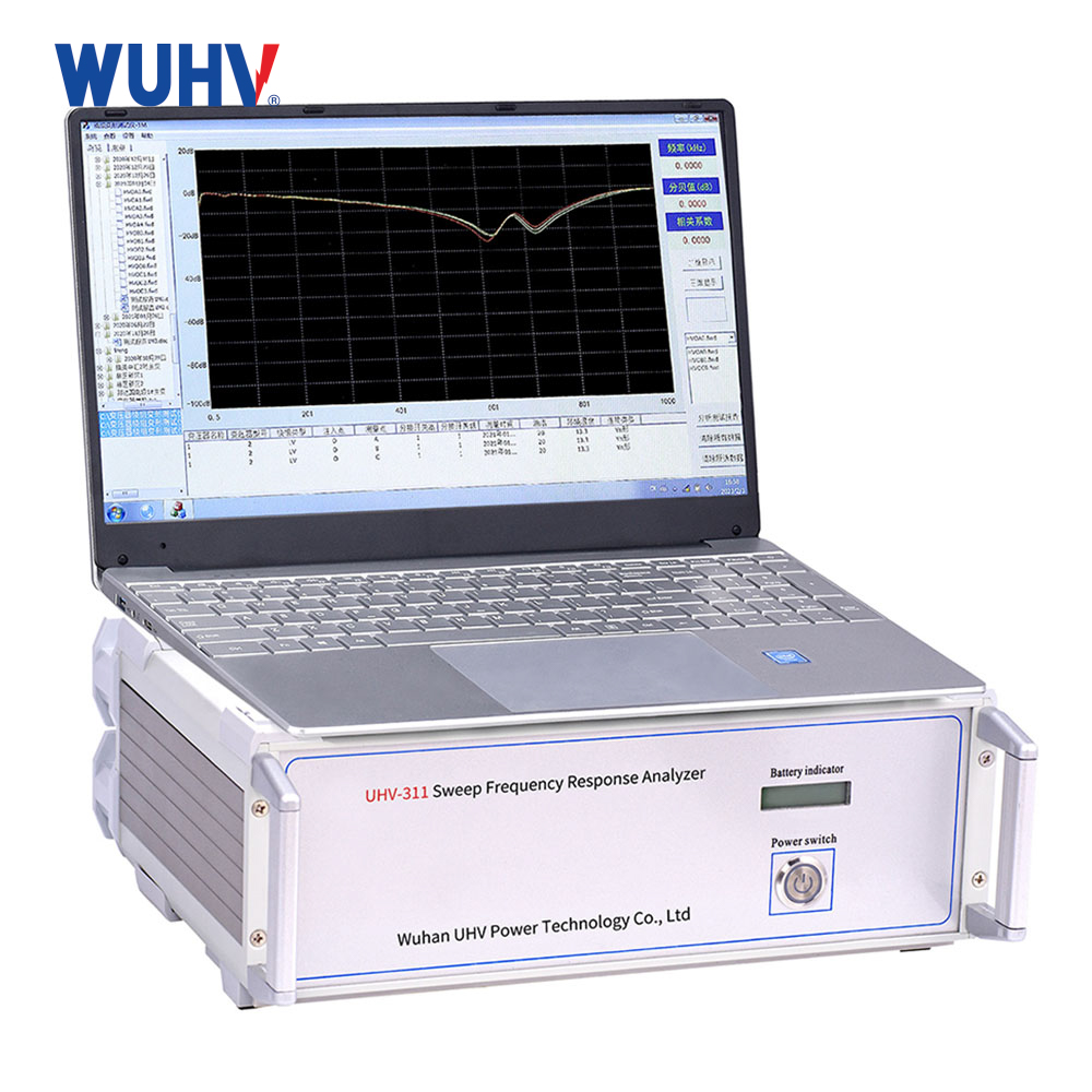
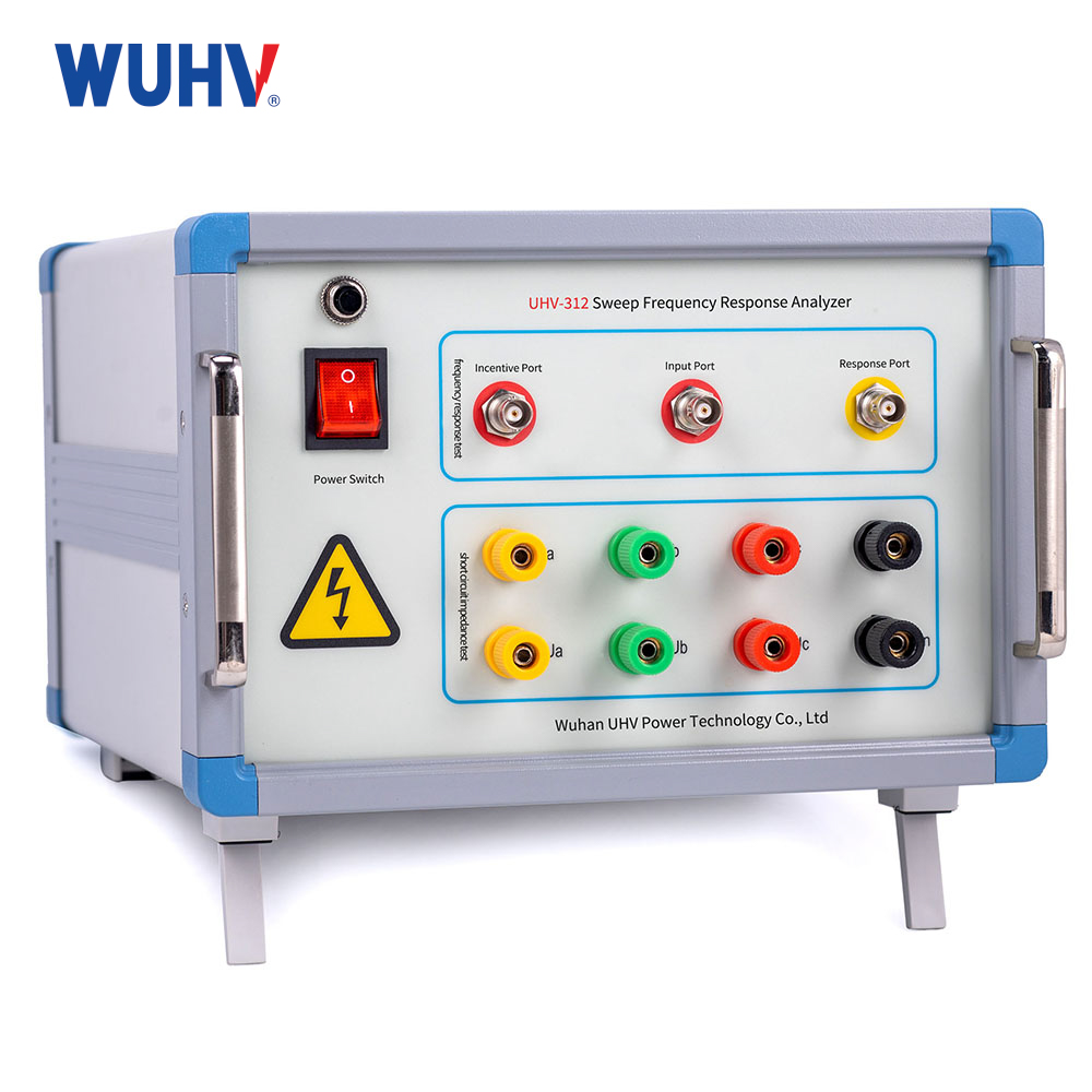
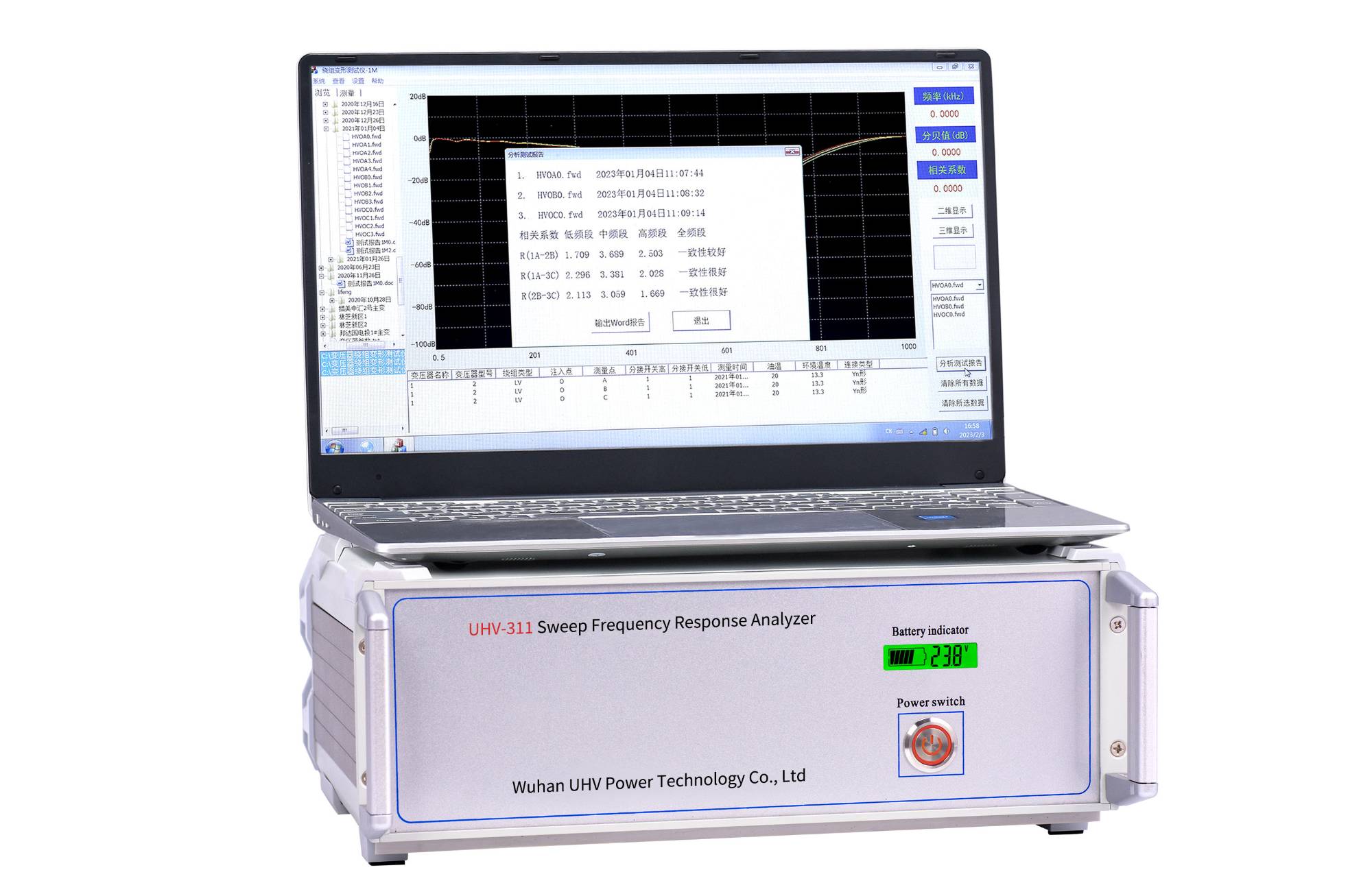
The transformer winding deformation tester is based on the measurement of the characteristic parameters of the internal winding of the transformer, and uses the internal fault frequency response analysis (FRA) method currently being developed in developed countries to accurately determine the internal faults of the transformer.
Ürün Özellikleri
1. Advanced DDS Core Technology
Dedicated digital high-speed scanning (DDS) detects:
Mechanical deformations (distortion/bulging/displacement/tilting)
Electrical faults (inter-turn shorts, phase-to-phase contact faults
2. High-Fidelity Acquisition System
SoC-controlled architecture with MIL-spec components
Dual-channel 16-bit A/D sampling (≥99.5% repeatability)
Field Validation: Tap changer operations induce significant waveform deviations
3. Dual-Sweep Measurement Modes
Linear + segmented frequency analysis compatible with domestic technical standards
4. Non-Invasive Testing Protocol
Requires only busbar disconnection; eliminates transformer disassembly
5. Ergonomic Field Operation
Measurement-insensitive lead configuration; technicians operate safely atop tank
6. Standards-Compliant Output
Meets national amplitude-frequency specifications (GB/T 1094.18)
User-selectable axis scaling: Linear or logarithmic plots
7. Intelligent Signal Control
Software-auto-ranged ±10V output with adaptive sampling frequency
8. High-Resolution Scanning
0-1MHz linear sweeps with configurable resolution (0.25/0.5/1kHz steps)
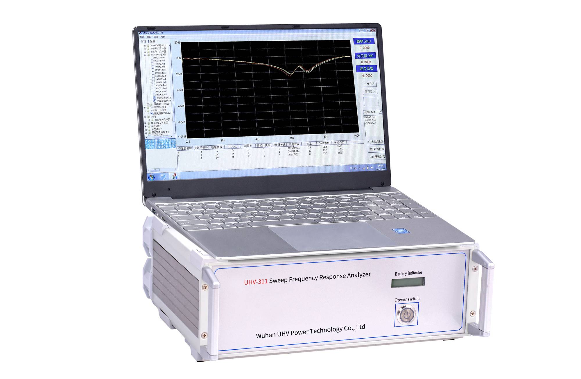
9. AI-Driven Diagnostics
6-curve historical comparison with axis-specific analysis
Automated parameter calculation & winding deformation diagnosis
Expert diagnostic conclusions
10. Automated Reporting Suite
Environmental parameter logging
Measurement data archiving
Word/PDF report generation with color printing
|  |
Teknik parametreler
| Linear frequency sweep measurement range | (1kHz)~(1MHz) |
| Segmented sweep frequency measurement range | (0.5kHz)~(1kHz) |
| (0.5kHz)~(10kHz) | |
| (10kHz)~(100kHz) | |
| (100kHz)~(500kHz) | |
| (500kHz)~(1000kHz) | |
| Range of amplitude | (-100dB)~(+20dB) |
| Accuracy of amplitude measurement | +20dB~-60dB;±1dB |
| -60dB~-100dB;±2dB | |
| Sweep accuray | 0.01% |
| Sinyal giriş empedansı | 1MΩ |
| Sinyal çıkış empedansı | 50Ω |
| In phase test repetition rate | 99.5% |
| Boyutlar | 300×340×120mm3 |
| Dimensions of Aluminum Alloy Packaging Box | 310×400×330mm3 |
| Ağırlık | 10 kg |
Technical Features
1. High precision measurement and analysis capability: This device adopts excellent digital signal processing technology to ensure good signal-to-noise ratio for signal generation and acquisition over a wide frequency range. Its measurement results have good repeatability, providing reliable basis for vertical (compared with its own historical data) and horizontal (between three phases) comparisons. Equipment usually has two analysis modes, amplitude frequency response and phase frequency response, which can reflect the condition of the winding from different dimensions, making diagnostic information more comprehensive.
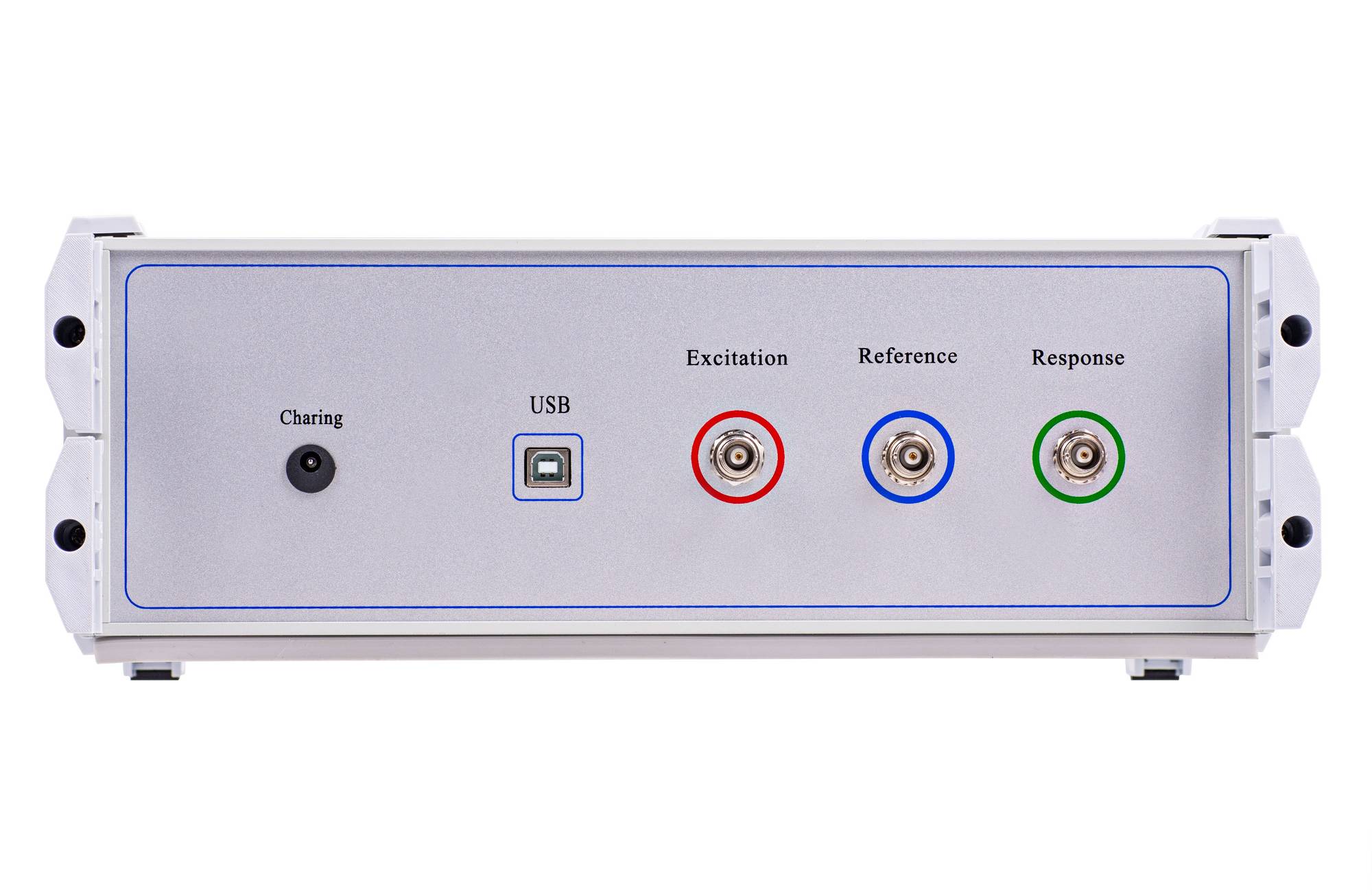
2. Humanized operation and data processing: Considering the usage habits of on-site engineers, this tester strives for a simple operation process. The testing wiring is clear and specific, and the accompanying specialized testing cables and fixtures effectively reduce contact resistance and external interference. The instrument has a built-in large capacity storage space, which can store a large amount of test data and curves. The supporting upper computer analysis software has clear functions and can perform various comparative analyses on test curves (such as correlation coefficient calculation, vector difference judgment, etc.), and generate standardized test reports, greatly simplifying later data analysis and archiving work.
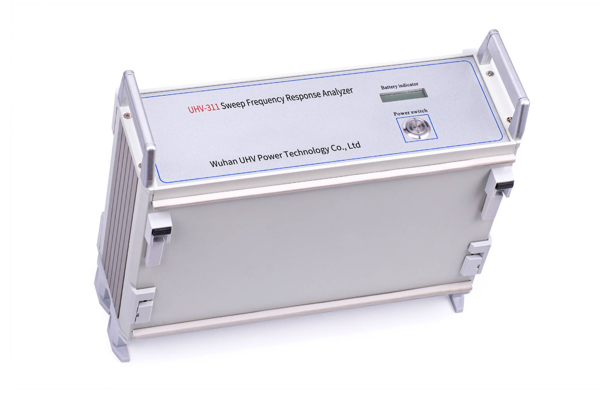
3. Stable performance and on-site applicability: The equipment is designed with full consideration of the complex electromagnetic interference environment on site, and has strong anti-interference ability. Its structure is sturdy, easy to carry, and suitable for use in on-site environments such as substations. The built-in high-performance lithium battery ensures the endurance requirements for long-term field operations, while supporting DC power supply, with good adaptability.
 |  |
Advantage
1. Non destructive testing to avoid secondary damage
2. High sensitivity, capturing small deformations
3. Quick and convenient, suitable for on-site use
4. Data traceability, supporting long-term tracking and analysis
5. Strong anti-interference ability and adaptability to complex environments
6. Economically, reduce operation and maintenance costs
7. Safe, low testing voltage, no risk of electric shock to operators
Application Scenarios
Factory acceptance and installation debugging: As a benchmark test for transformers before leaving the factory or being newly installed and put into operation, establish a "fingerprint" map.
Post accident state diagnosis: After the transformer is subjected to near-field short-circuit impact, timely testing is carried out to determine whether its internal structure is damaged, providing key basis for deciding whether to immediately shut down and carry out maintenance.
Post transportation inspection and regular maintenance: Testing is conducted on transformers after long-distance transportation or in conjunction with regular power outage maintenance to track the stability of their winding status and achieve condition based maintenance.
Frequently Asked Questions
1. Does the tester need to be preheated? Why are the curves measured in the morning and afternoon different?
need The high-frequency oscillator inside the instrument has frequency drift due to temperature effects. It is recommended to preheat for 15-30 minutes after turning on the machine before starting the test. In addition, drastic changes in environmental temperature (such as large temperature differences between morning and evening) can alter the dielectric constant of transformer oil, leading to weak drift in the high-frequency range. This is a normal physical phenomenon, not winding deformation.
2. Do the leads (busbars) on the transformer bushing need to be removed during testing?
Strongly recommend dismantling. Undismantled overhead lines or enclosed busbars can introduce additional ground capacitance and inductance, altering the high-frequency resonance curve and leading to distorted test results, making it easy to misjudge.
If it is impossible to disconnect the wires on site (such as GIS enclosed busbar), the test results must be marked as "with busbar status" and can only be compared vertically with historical data of the same "with busbar status", and cannot be compared horizontally with factory "bare transformer" data.
3. How to determine if the winding is deformed?
Determine through horizontal comparison (consistency of frequency response curves of three-phase windings) or vertical comparison (differences between current data and historical spectra). Winding deformation can cause changes in the frequency response curve, such as resonance frequency offset and abnormal amplitude attenuation. The degree of deformation can usually be divided into: normal winding, mild deformation, obvious deformation, and severe deformation.