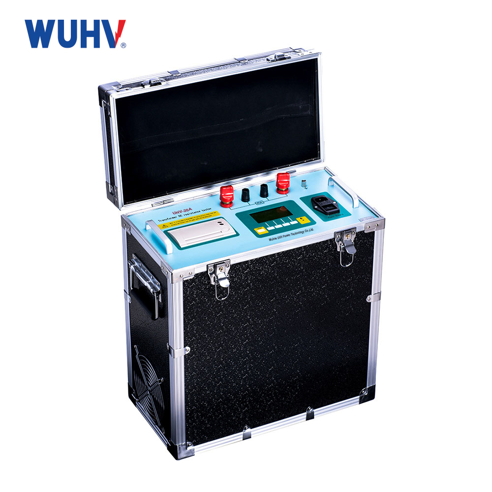
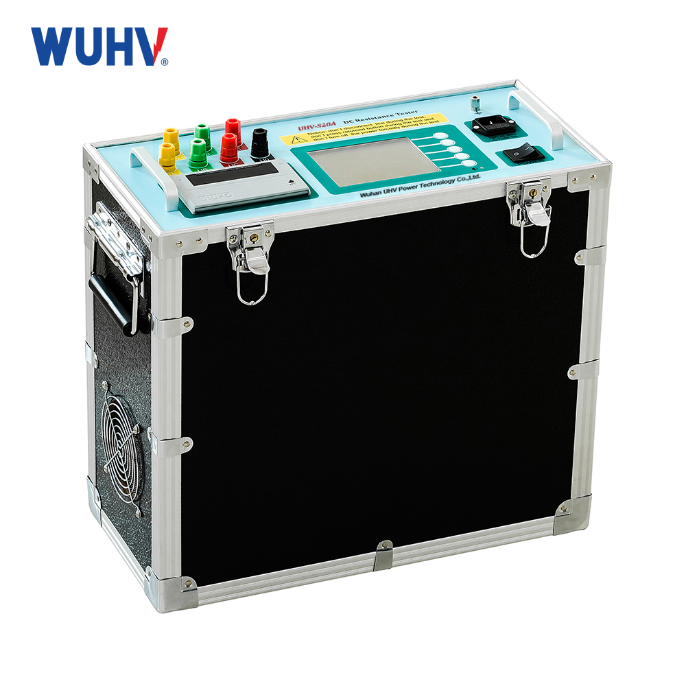
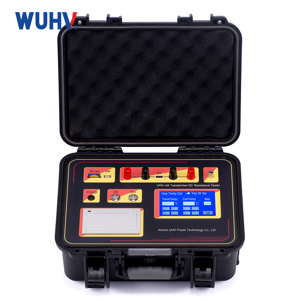
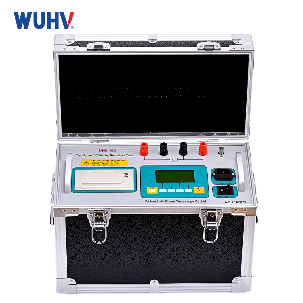
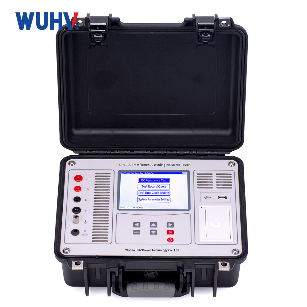
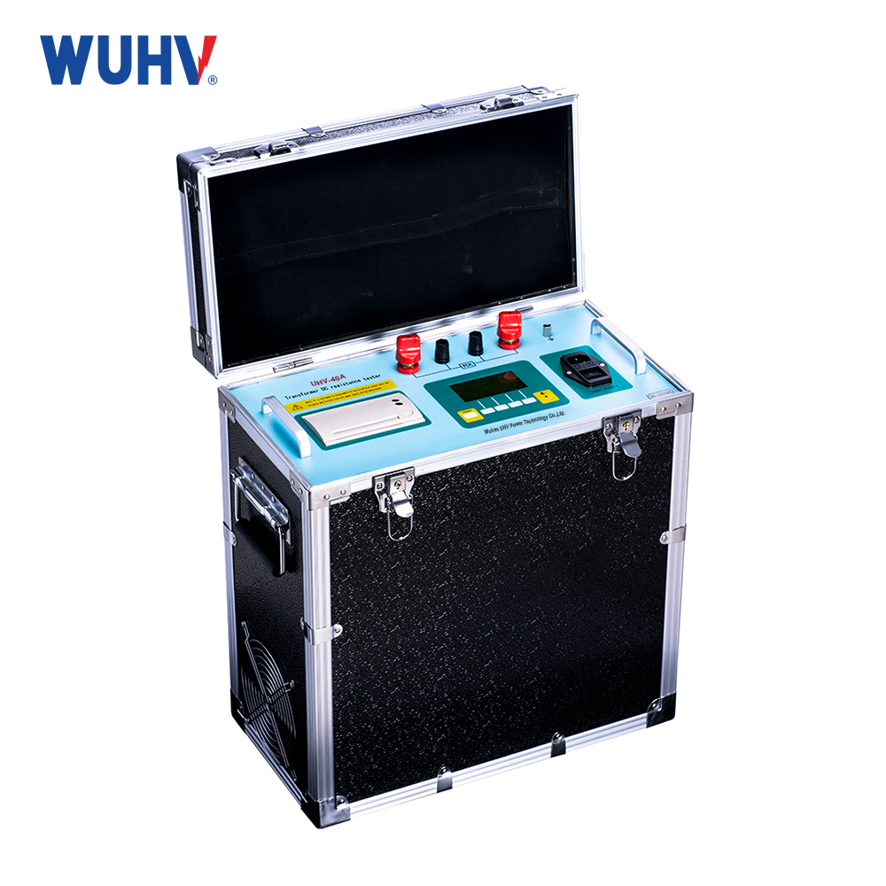
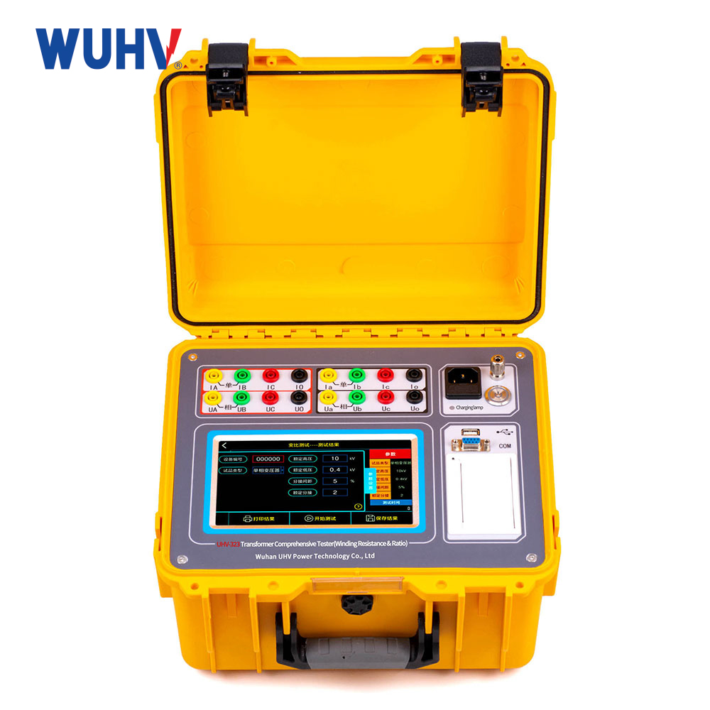
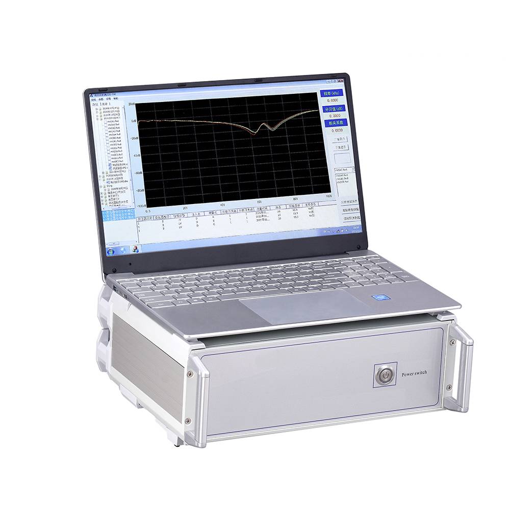
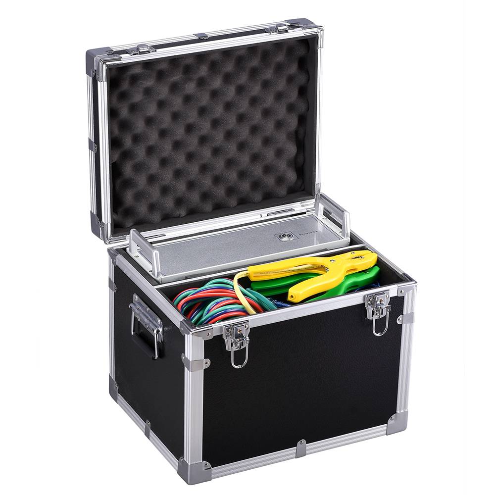
Sweep Frequency Response Analyzer
Product Introduction
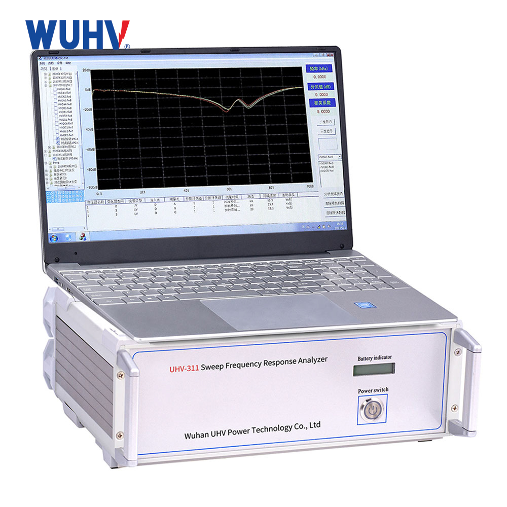
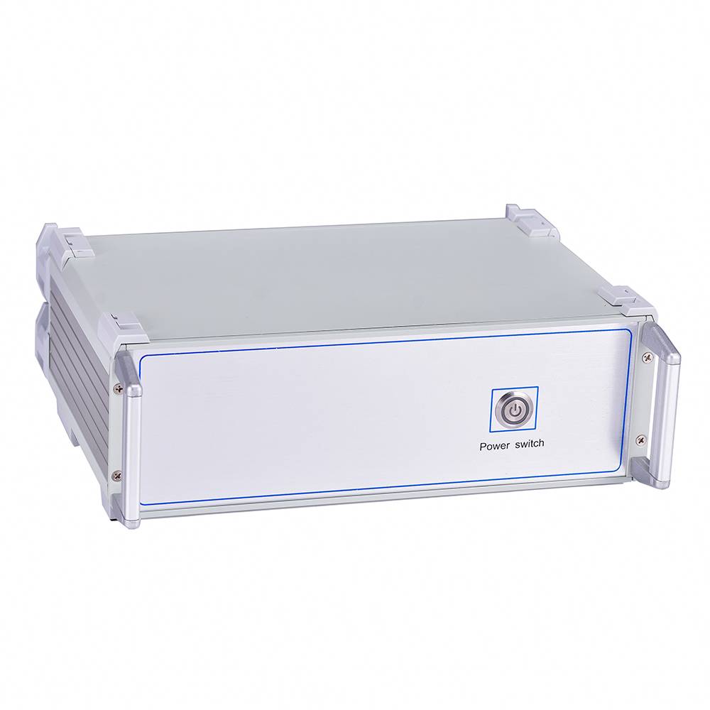
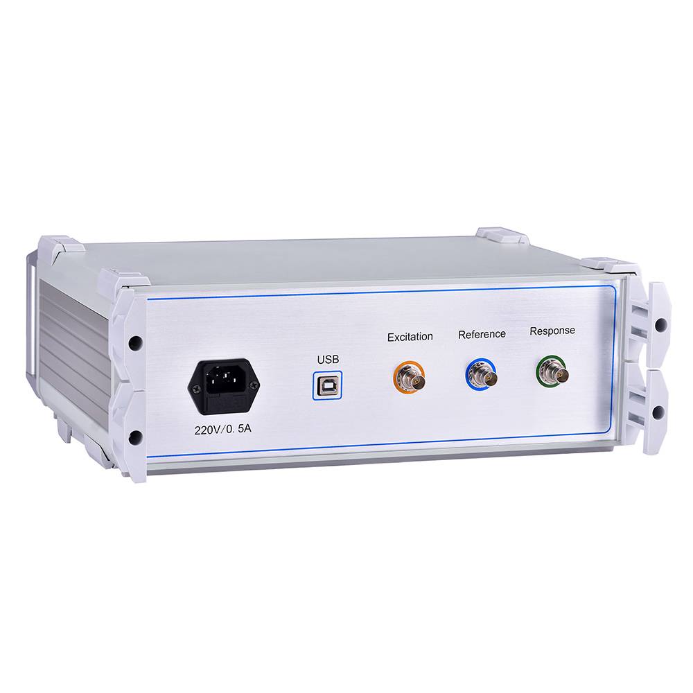
The transformer winding deformation tester is based on the measurement of the characteristic parameters of the internal winding of the transformer, and uses the internal fault frequency response analysis (FRA) method currently being developed in developed countries to accurately determine the internal faults of the transformer.
Technical Features
1. High-Performance Core Control – Utilizes a high-speed, highly integrated microprocessor for precise data acquisition and control.
2. USB Communication – Supports direct USB interface connection to laptops for seamless data communication.
3. Wireless Bluetooth Connectivity – Enables wireless data exchange between instrument and laptop for flexible field operation.
4. Advanced DDS Sweep Technology – Adopts digital frequency-sweep technology (USA) to accurately diagnose winding distortion, bulging, displacement, tilting, inter-turn short circuits, and inter-phase faults.
5. High-Resolution Dual-Channel Acquisition – Features dual-channel 16‑bit A/D with high-resolution dB‑value measurement for superior signal accuracy.
6. Software-Adjustable Output – Output amplitude adjustable via software, with peak output up to 10 V.
7. Automated Reporting – System automatically generates test reports in electronic Word format.
8. High Stability & Repeatability – Built with precision, high‑stability components; measurement repeatability exceeds 99.5% for the same winding phase.
9. Robust Hardware Design – Finished circuit boards are specially surface‑treated for resistance to moisture and corrosive gases.
10. Flexible Measurement Modes – Combines linear and segmented frequency‑sweep modes, compatible with mainstream domestic technical methodologies.
11. Compliant & Adaptable Display – Meets national technical standards for amplitude‑frequency characteristics; supports both linear and logarithmic frequency axes, allowing users to select the most suitable format for report printing.
 |  |
Teknik parametreler
| Linear frequency sweep measurement range | (1kHz)~(1MHz) |
| Segmented sweep frequency measurement range | (0.5kHz)~(1MHz) |
| (0.5kHz)~(10kHz) | |
| (10kHz)~(100kHz) | |
| (100kHz)~(500kHz) | |
| (500kHz)~(1000kHz) | |
| Range of amplitude | (-100dB)~(+20dB) |
| Accuracy of amplitude measurement | +20dB~-60dB;±1dB |
| -60dB~-100dB;±2dB | |
| Sweep accuray | 0.01% |
| Sinyal giriş empedansı | 1MΩ |
| Sinyal çıkış empedansı | 50Ω |
| In phase test repetition rate | 99.5% |
| Boyutlar | 300×340×120mm3 |
| Dimensions of Aluminum Alloy Packaging Box | 310×400×330mm3 |
| Ağırlık | 10 kg |
Main advantages
1. Non destructive testing is the core feature, and the testing process does not require disassembling the transformer or applying high voltage. Evaluation can be completed through low-voltage sweep signals without affecting the normal operation of the equipment.
2. High sensitivity, able to identify subtle geometric changes in windings, such as small variations in the distance between winding lobes or slight bending of wires, which are difficult to detect in traditional DC resistance testing or insulation resistance testing.
3. Good repeatability, the test results of the same equipment at different time points are comparable, making it easy to establish long-term monitoring records and track the trend of changes in winding status.
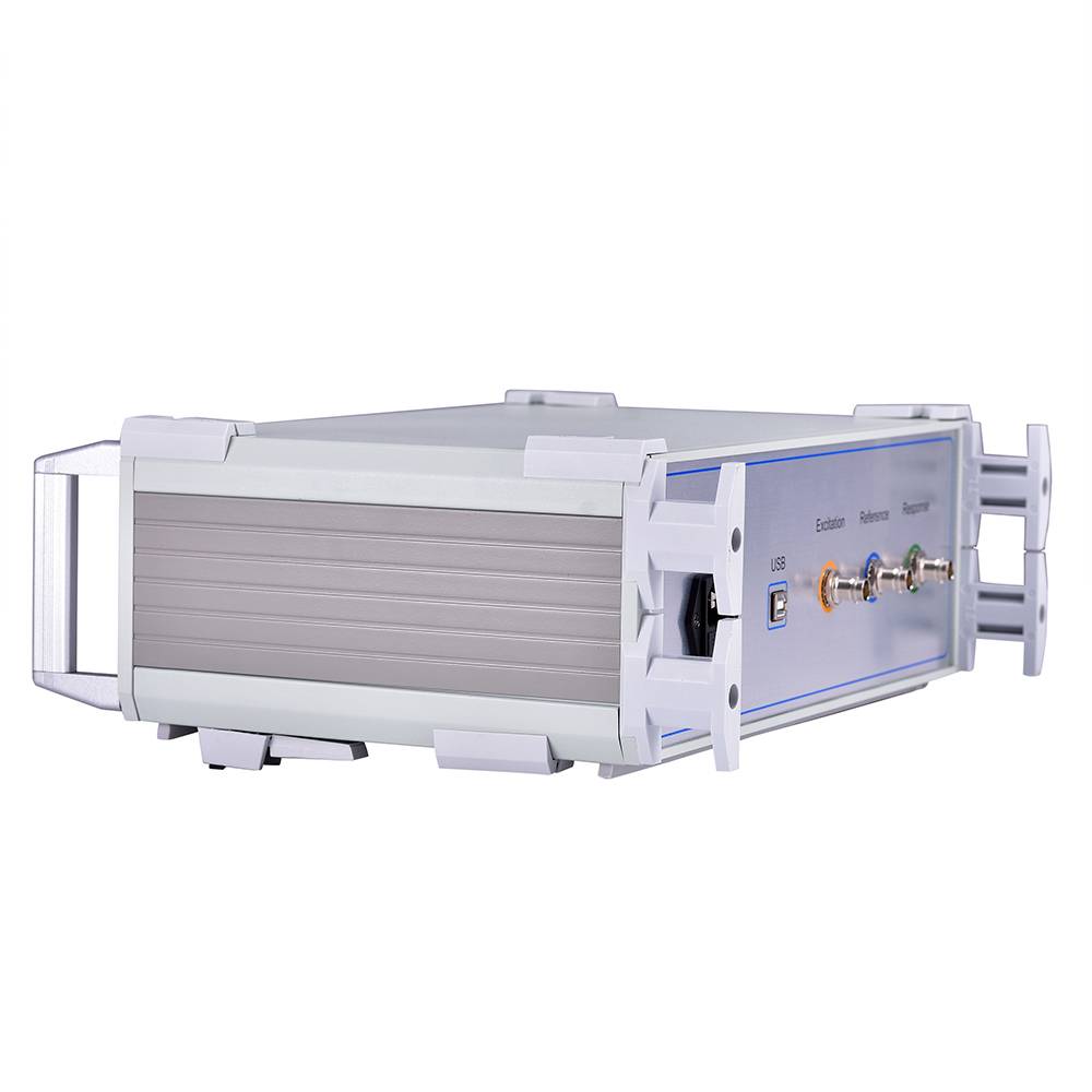
4. The testing efficiency is high, and a single scan usually takes only a few minutes. The instrument is compact in size and easy to carry, making it suitable for on-site inspections.
5. Strong anti-interference ability, modern testing equipment adopts digital filtering and shielding technology, which can obtain stable data in electromagnetic noise environments such as substations.
6. The data storage and comparison function is complete, and the instrument can save multiple sets of historical curves, automatically calculate correlation coefficients or deviation indicators, and assist technicians in quickly locating abnormal frequency bands.
 |  |  |
Main application scenarios
Handover acceptance test: Before the new transformer is put into operation, establish the original fingerprint spectrum and impedance data of the winding as the basis for future comparison.
Post fault diagnosis: After the transformer is subjected to output short circuit or near-field short circuit impact, it is immediately tested to determine whether the winding is damaged and whether it can be put back into operation.
Inspection after major overhaul or transportation: Verify whether the mechanical structure of the winding of the transformer remains in good condition after long-distance transportation or major overhaul of the suspension cover.
In operation status assessment: Regular physical examinations are conducted on transformers that have been in operation for a long time or have a history of abnormal vibration to evaluate their health status.
Typical Case
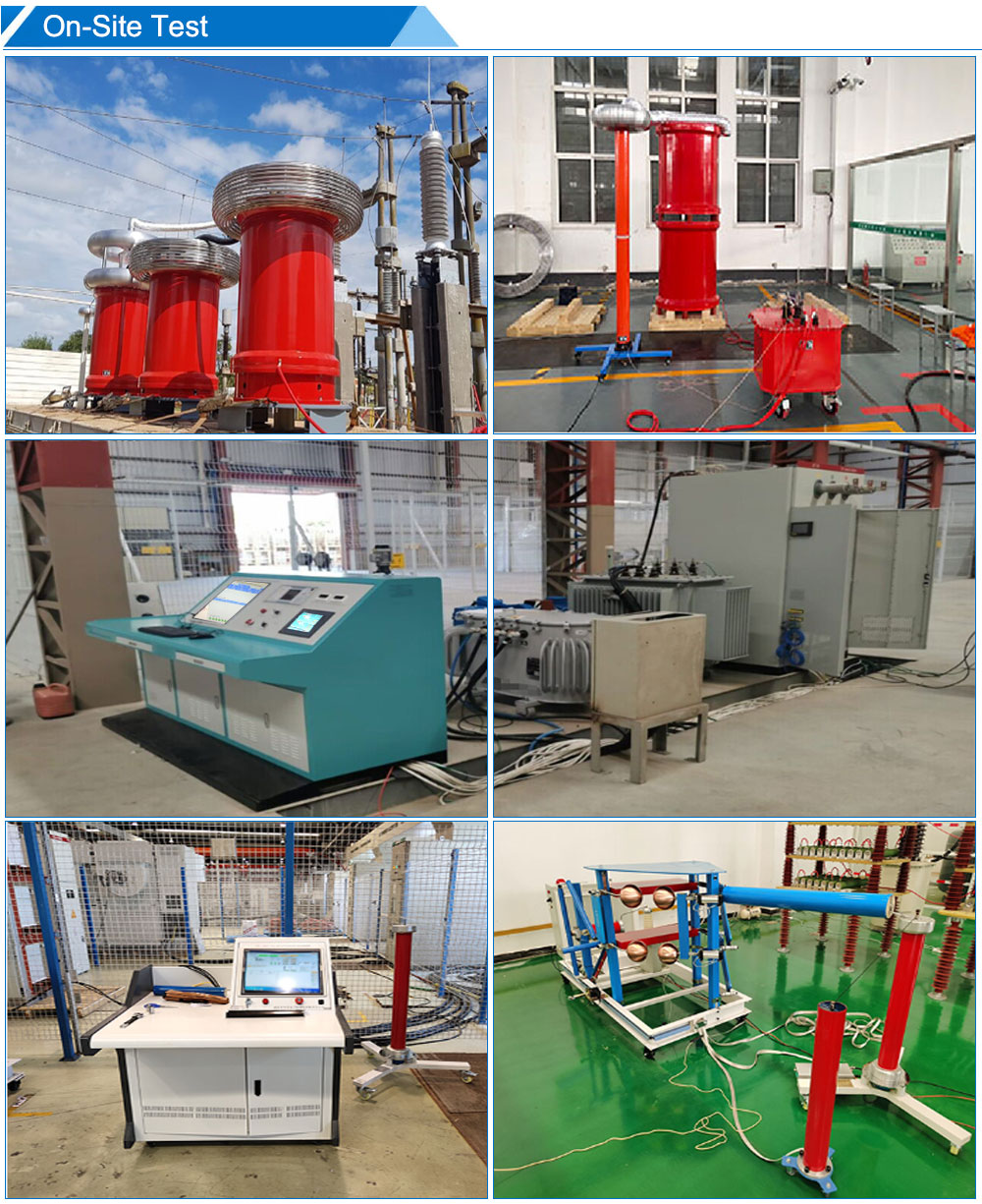
This instrument has been applied in multiple on-site testing scenarios, and the following are two representative practical cases:
Case 1: State assessment of a 110kV main transformer after short-circuit surge. A 110kV main transformer in a substation in a certain area was subjected to short-circuit current surge due to a line fault. To ensure the safety of the equipment, the testing personnel conducted an emergency test on the transformer using the Wuhan UHV winding deformation tester. By collecting and comparing the frequency response data of the three-phase winding horizontally, it was found that one phase had a resonance point offset phenomenon in the mid to high frequency range. Based on this discovery, the user arranged further tracking and monitoring of the transformer, providing necessary technical basis for subsequent maintenance decisions.
Case 2: Network detection of newly built data center distribution transformers Before a large data center is put into operation, it is necessary to conduct a winding status survey of 20 10kV dry-type distribution transformers. The testing team used this tester to complete the winding deformation testing of all transformers and established an initial state database for the equipment, providing benchmark data for future preventive tests.
Frequently Asked Questions
1. What is the difference between Frequency Response Analysis (SFRA) and Short Circuit Impedance Analysis (LVI)?
Frequency response method (SFRA): With extremely high sensitivity, it can detect small mechanical displacements (such as 1-2mm distortion) and mainly measure characteristics in the high frequency range (>100kHz).
Short circuit impedance method (LVI): reflects the overall average deformation of the winding, is sensitive to severe radial bulges, and measures the leakage impedance value at power frequency (50Hz).
2. Is the test signal harmful to the human body or transformer?
Absolutely safe. The output signal of the tester usually has an AC voltage of only 10V~20V and a very small current (mA level), which belongs to low-voltage non-destructive testing and does not pose a risk of aging or breakdown to transformer insulation.
3. What should I do if the instrument cannot start normally?
It may be a power failure or an internal malfunction of the instrument. Firstly, check if the power supply is connected properly and if there is voltage output. If the power supply is normal, it may be an internal malfunction of the instrument, and after-sales service should be contacted for repair.